When you click on links to various merchants on this site and make a purchase, this can result in this site earning a commission. Affiliate programs and affiliations include, but are not limited to, the eBay Partner Network.
In preparation for my DJ Qube blue dash which I've already received part of when I had him do the audio controls, I felt the need to have my Defi BF Gauges match what will be the rest of my cluster color.
I did not feel like investing a lot of money to do this and I wasn't entirely sure how the gauges were constructed. So, I pulled them apart to see what I could do.
Tools required:
1 small flat head screwdriver
1 #2 Phillips head screw driver
1 #1 Phillips head screw driver
1 Blue Sharpie (or any color you desire)
Step one: Gently pry the back of the gauge face cover that is flanged to hold it onto the gauge back casing with a small flat head screwdriver. Be very careful with this as you can damage the flange easily so that it is visible when you reassemble it. Do this on about 3/8s of the flange. Gently pull the gauge face cover off, it will take a little bit of effort as you pull the back casing off at an angle. If you want, you can bend the entire flange to make this easier but it's not necessary. You may want to cover the screwdriver head with tape to avoid scraping the flange.
Step two: Remove the two screws retaining the gauge back casing. Remove the gauge casing.
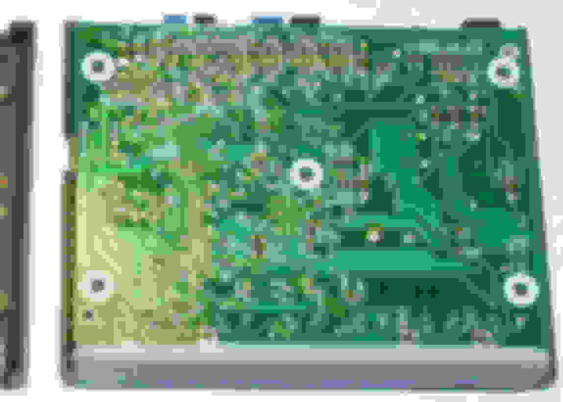
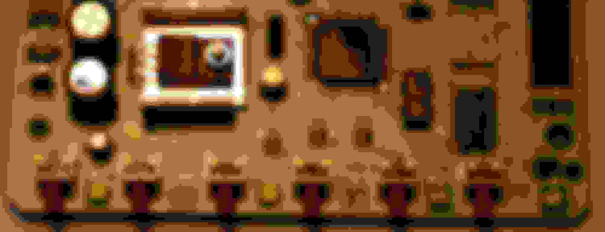
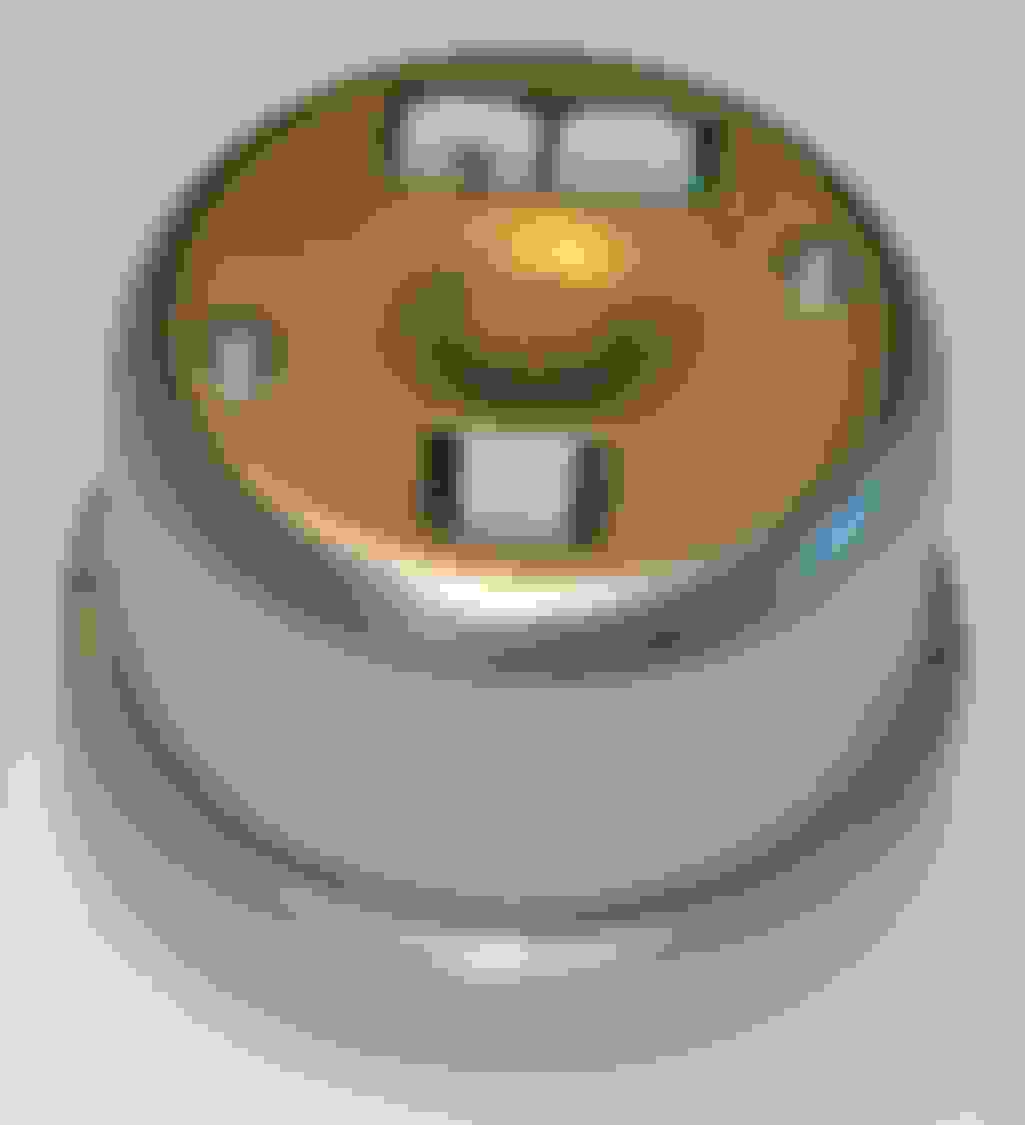
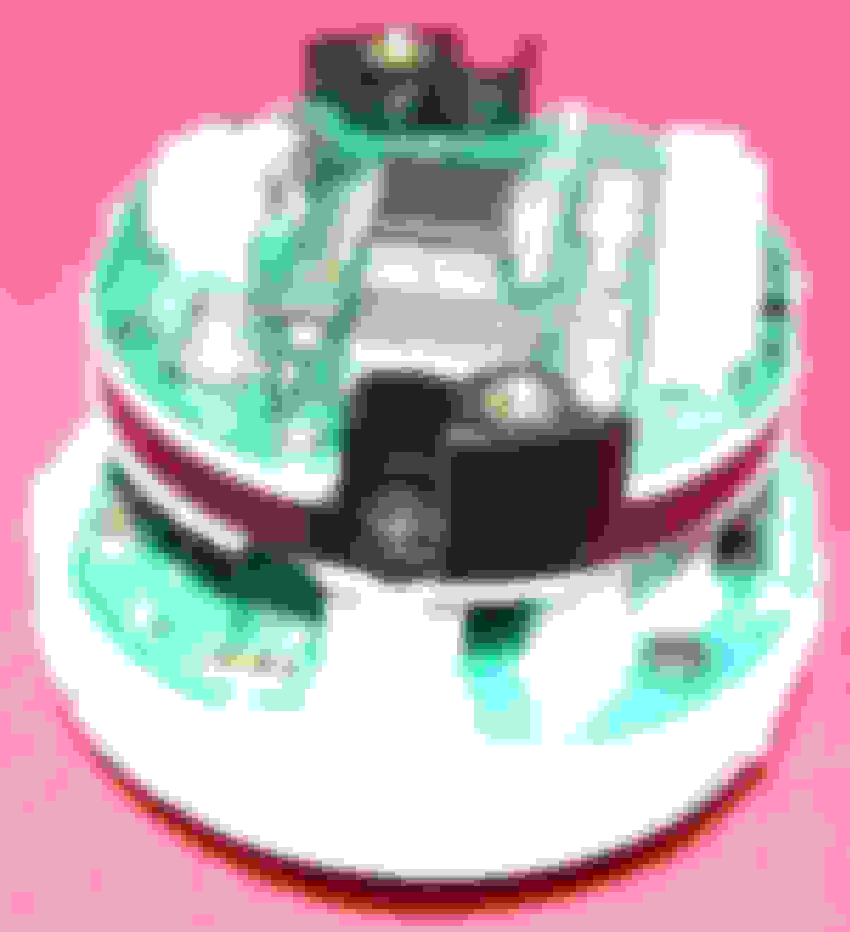
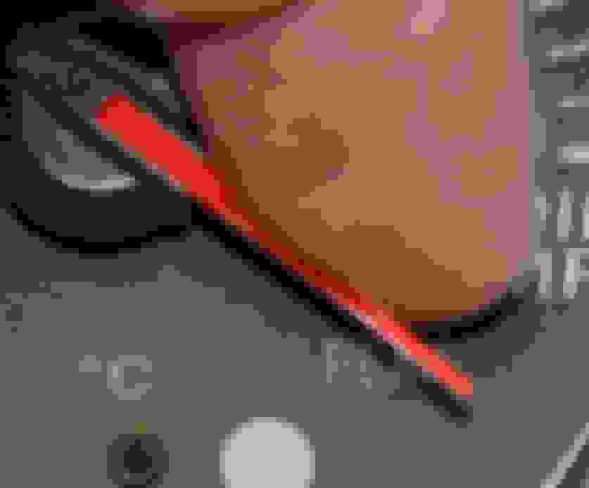
Step three: Remove the two black screws that are recessed in the black plastic portion of the gauge (see image above). Gently remove the dual board. This will take a bit of effort as this piece has the gauge needle attached. Be sure to pull straight back to get the needle out of the mechanism. Be careful not to bend the needles pin. Also be careful not to bend the electrical connecting ping on the board below.
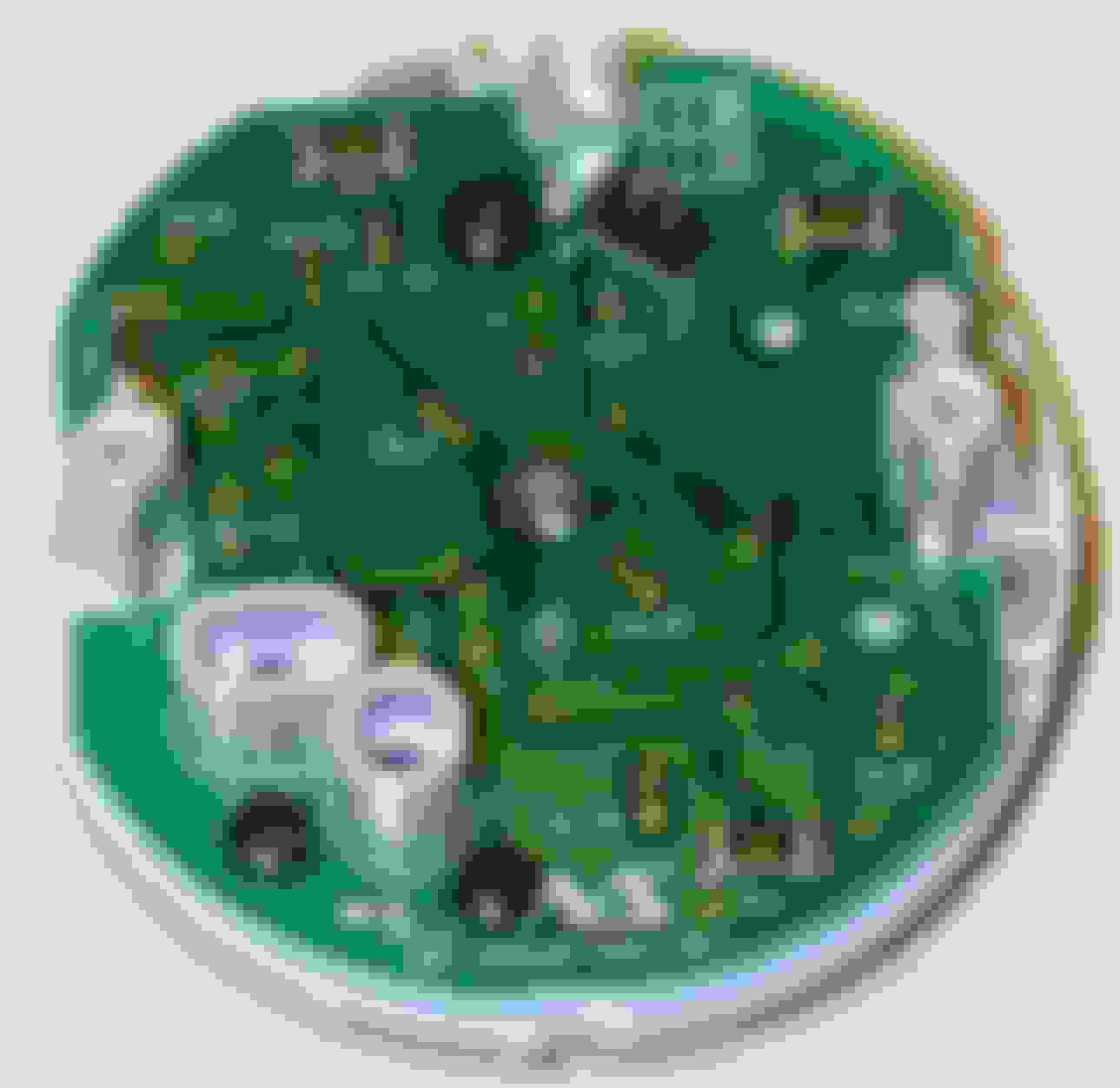
Step four: Remove the three black screws on the board and gently pull it off of the gauge face. There is another set of electrical connector pins on this piece as well.
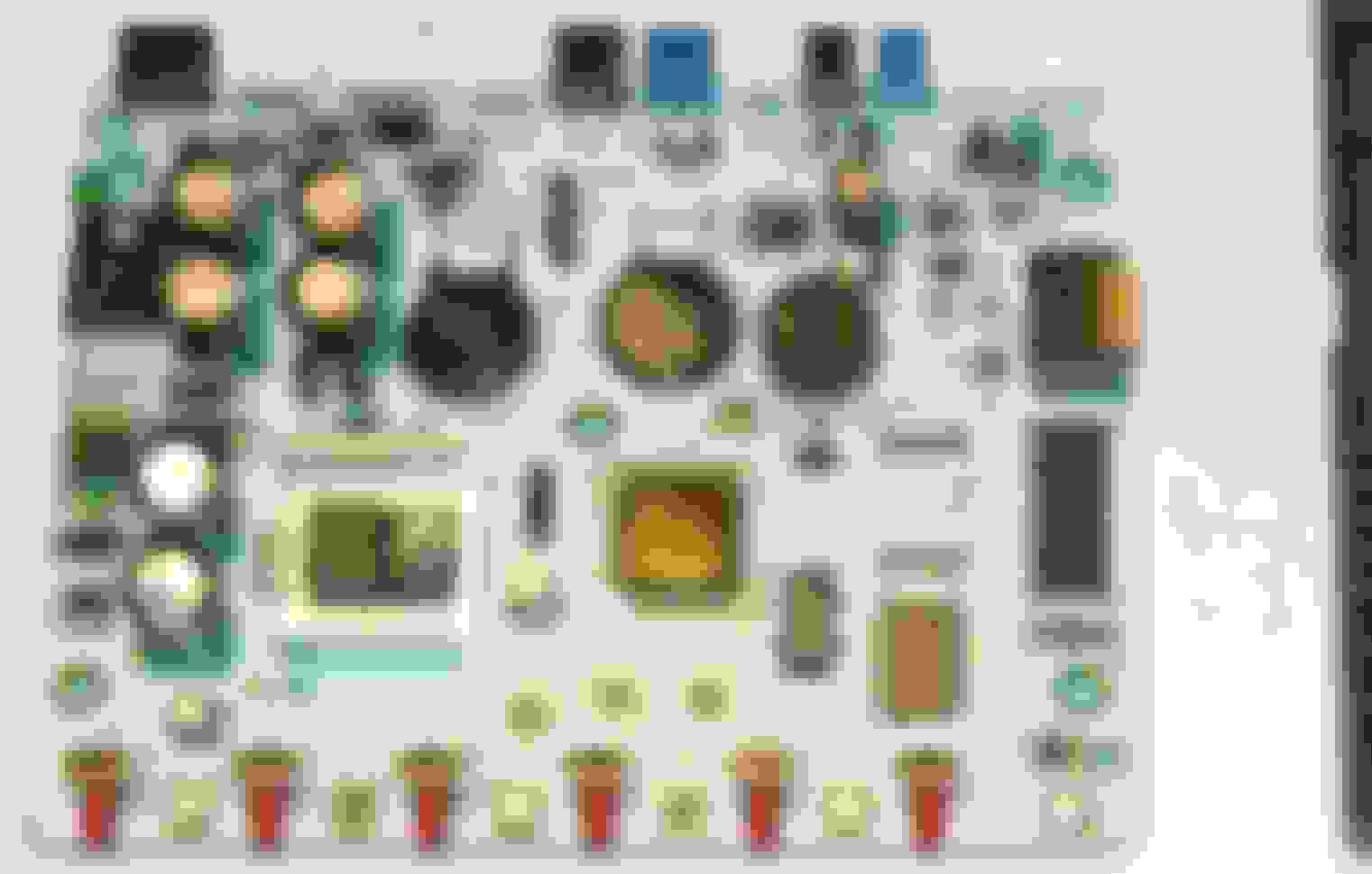
Step five: Take a blue Sharpie (or whatever color you desire) and color each of the 8 rectangular LEDs, you may want to go over them a few times to darken your color choice when they are lit.
Step six: Reassemble the gauge pieces in reverse order. I don't know the torque settings for the screws but do not overtighten the once that are in direct contact with the circuit board, you don't want to crack it. The board with the colored LEDs can only go one way onto the back of the gauge face but the board that goes on top of the LED board can go back on the wrong way. There are electrical pin connectors that must connect, be careful not to bend the male ends.
The last dual board also has connectors that must connect to the lower board. Tighten down the two recessed screws.
Step seven: The gauge needle is calibrated and you may loose calibration by a significant degree. From my best guess the calibration is set with the needle touching the stopper pin. You can get close to this if you insert the needle pin part way until it engages the control mechanism
Gently rotate it until it hits the mechanism stop point at 0.
If this point has the needle beyond the stopper pin, rotate the needle all they way up to the higher mechanism stop point and then push the needle a bit further to rotate it. Don't man handle it, I don't know the strength of the mechanism.
Rotate it back down to see where it stops at the low point. Repeat this process until the needle appears to be at the stopper pin at the low point and press the needle completely down into the mechanism.
Step eight: Reassemble the gauge back casing and tighten down the two screws. Be sure the daisy chain connectors are in the proper holes on the casing. Slip the gauge face cover back over the lip of the back casing. Bend the flange back over. I used the back of a screwdriver to get a nice smooth bend and you may want to gently press it back with a tape covered screwdriver tip to get a better fit.
Step nine: Reconnect the daisy chain wires from the control unit and fire it up
If you find that the gauge is completely off calibration, there is a calibration control on the back of the dual board section, this can be adjusted with a small flat head screwdriver and you may want to check it against your known readings before you began this process. Or you can adjust the needle accordingly before you press it all the way down. You can check this before you reassemble the gauge casing by connecting the daisy chain wires and turning them on.
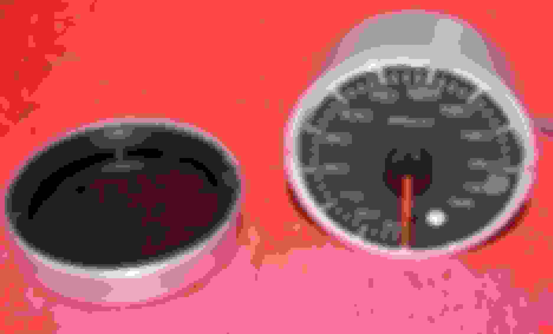
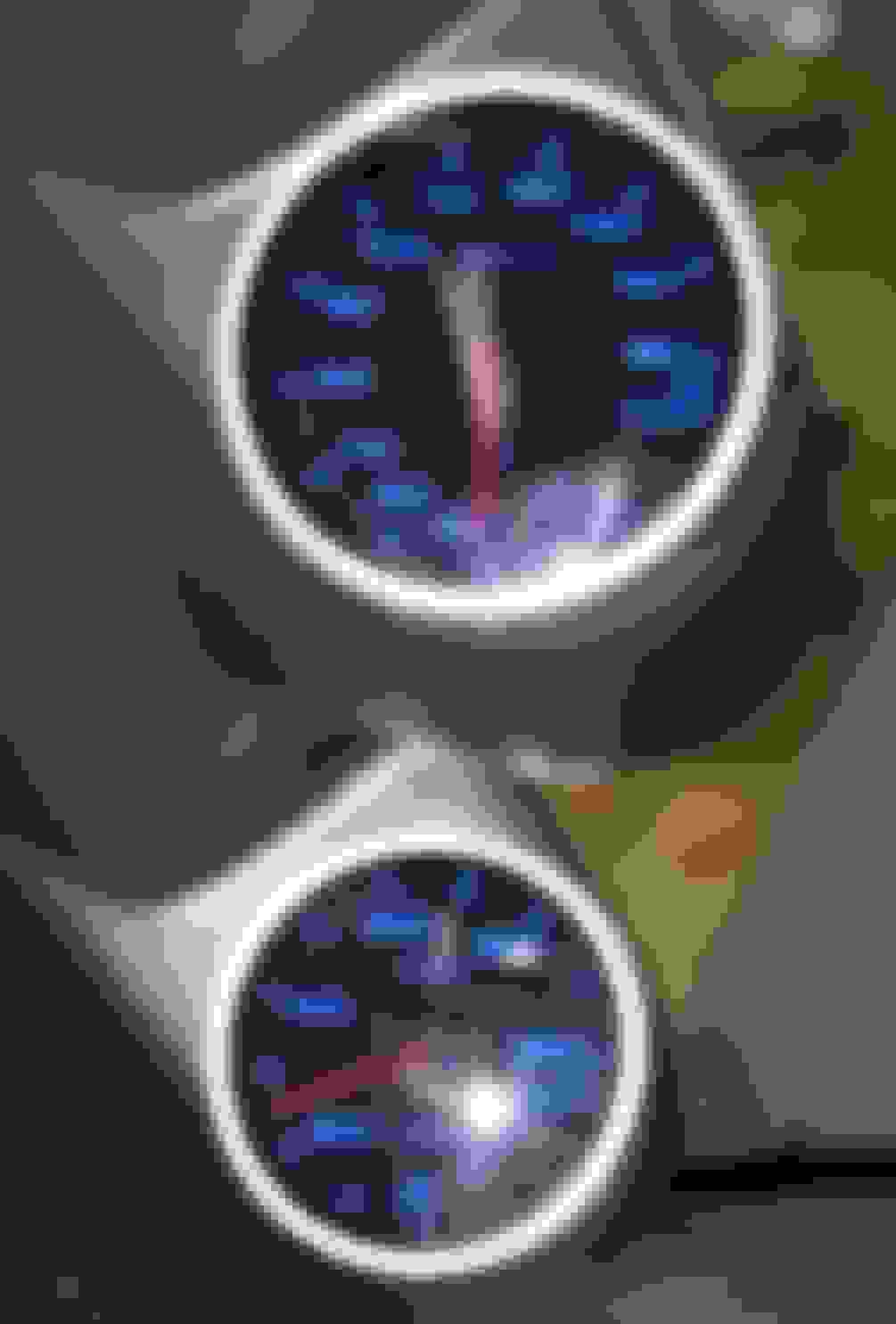
Startup and power down is the same, the fade out with the power off will still light up the gauge face in red as the colored LEDs are off and the red light comes from the center LED cluster that lights the needle.
Marcus, you win my award for best electrical engineering project where nothing electrical was done You get two for that one...keep that up and you'll put guys like me out of business.
The control unit is normally lit up white when the lights are on and during initial power up with the lights off.
Step one: Remove the five crews holding the control unit casing together
Step two: Lift off the upper portion of the casing
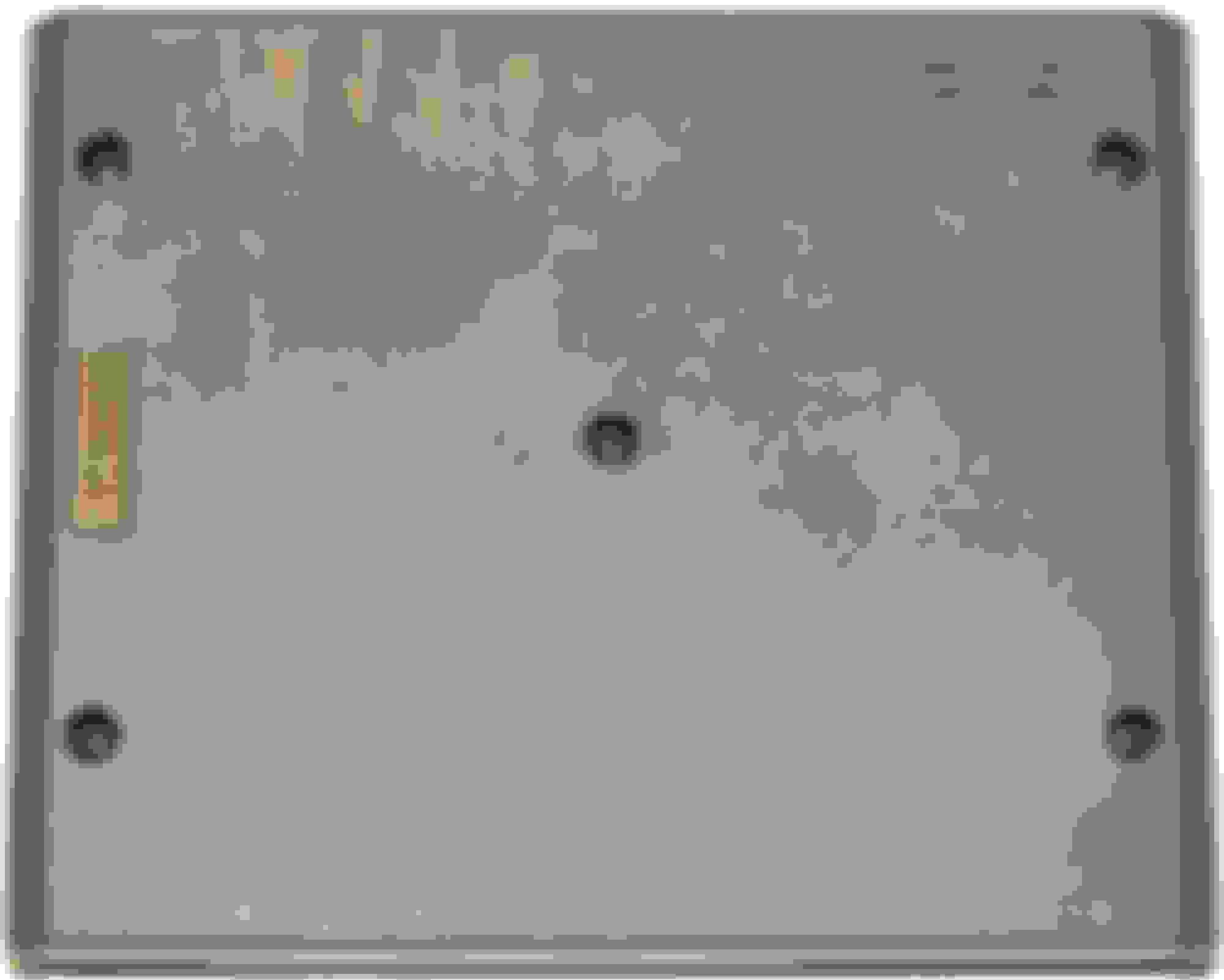
Step three: Lift out the circuit board from the lower portion of the casing. There is one screw located off center on the circuit board, DO NOT REMOVE THIS SCREW. It is a retaining screw for a component on the other side of the board.
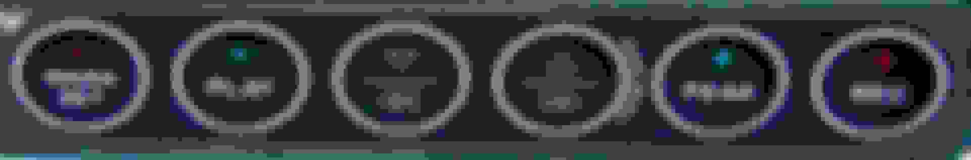
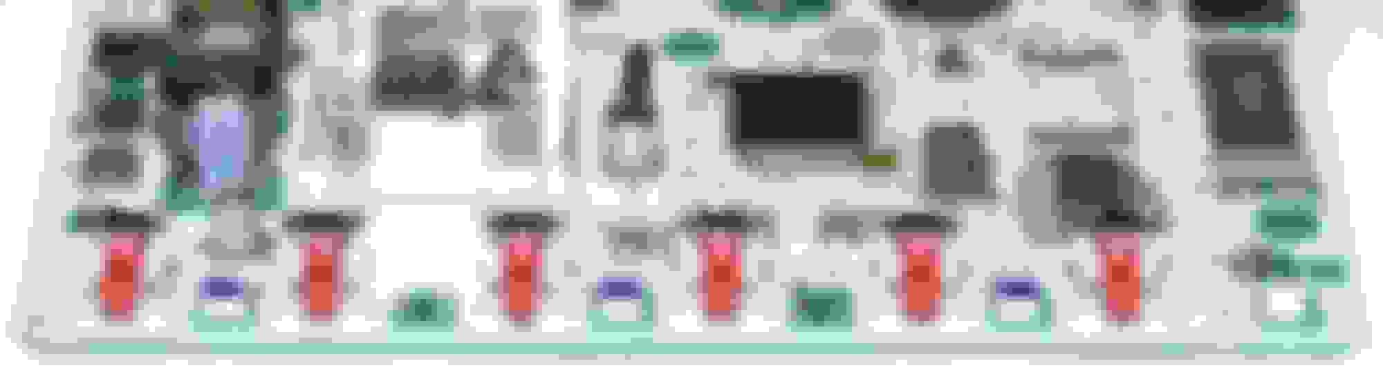
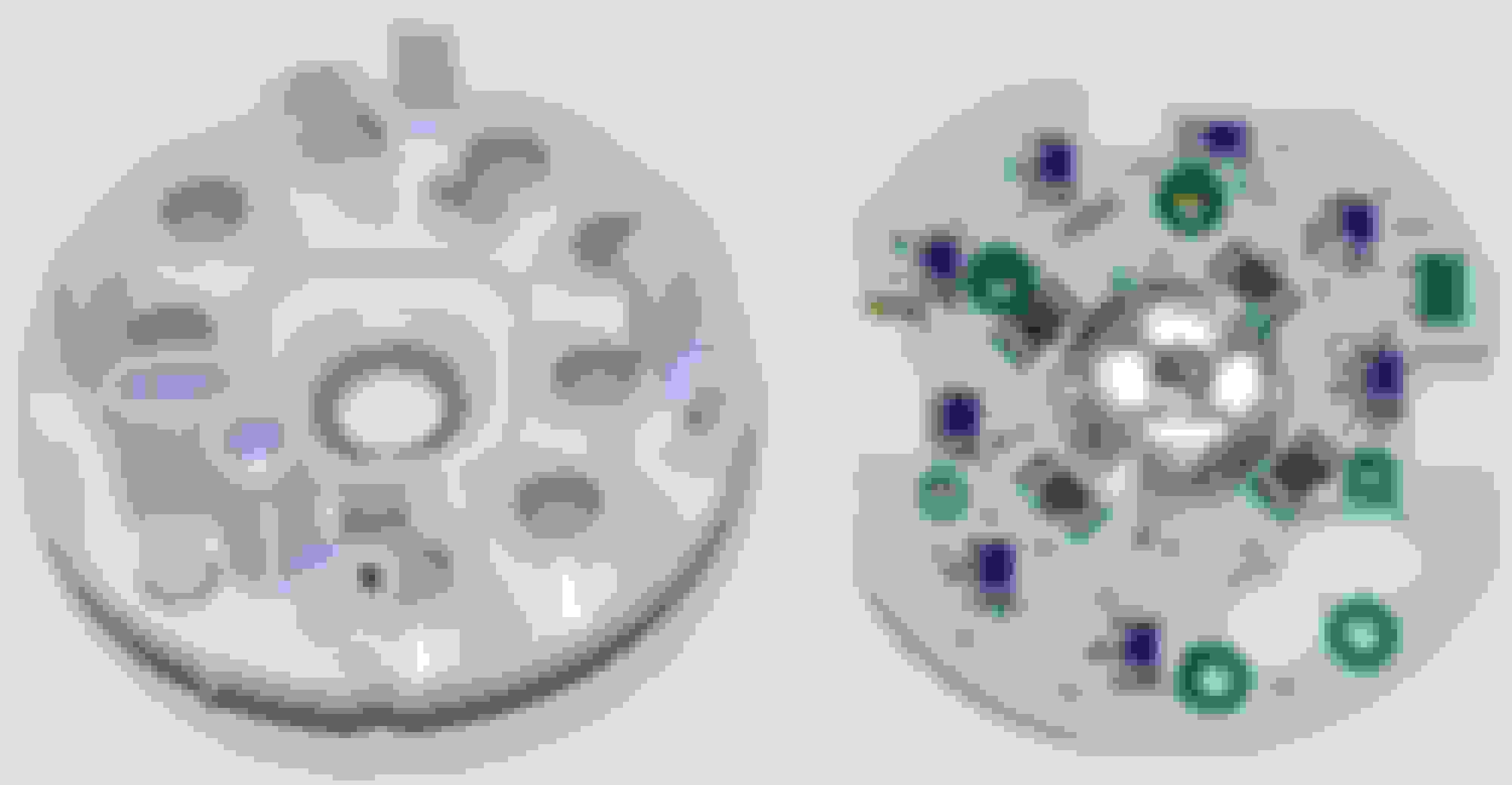
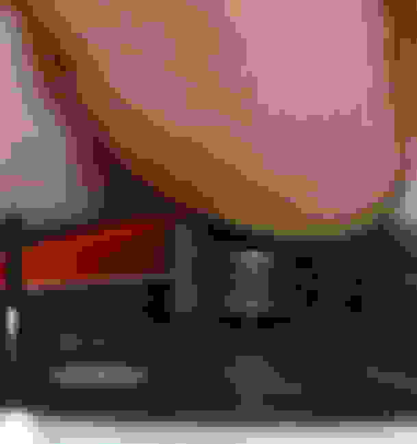
Step four: Locate the four LEDs on the top of the circuit board. LED! is the differential pressure warning light and is located on the far right side of the board. The numbering of the LEDs on the board is a bit screwy, LED2 is located on the far left of the board and from left to right, they are numbered LED2, LED4, LED3, LED5, LED6. Only LED2, LED3 and LED6 have actual LEDs in them.
Step five: Take a blue Sharpie (or any color of your choice) and color the tops of LED2, LED3 and LED6.
Step five: Reassemble the the unit back into the casing. There is an alignment pin on the case that coresponds with the alignment hole on the board. It can only go back together one way (unless you force it and break the alignment pin). Put the five screws back in and tighten down (not too tight, you're screwing into plastic and it can easily strip)
Step six: Reconnect to your vehicle wiring and light it up.
 10-14-2003, 02:24 AM


 Marcus, you win my award for best electrical engineering project where nothing electrical was done
  You get two
  for that one...keep that up and you'll put guys like me out of business.