GReddy EMU vtec wiring
 01-07-2012, 07:21 PM
#1
Registered User
Thread Starter

Join Date: Jan 2008
Location: Oxford
Posts: 997
Likes: 0
Received 0 Likes
on
0 Posts
How to do this? There are so many diagrams but no 100% on whichever one that it works.
I tried vtec solenoid to ecu cut and wire solenoid into the emu. I'd like to use auxiliary map to control the vtec.
Please help!! I need it illustrated and worded.
I get from some wording the solenoid (engine side) does not need to be connected to anything. I'm just confused.
Help!!! :'(
I tried vtec solenoid to ecu cut and wire solenoid into the emu. I'd like to use auxiliary map to control the vtec.
Please help!! I need it illustrated and worded.
I get from some wording the solenoid (engine side) does not need to be connected to anything. I'm just confused.
Help!!! :'(
 01-08-2012, 03:46 AM
#2
Registered User

Join Date: Jul 2006
Location: The Netherlands
Posts: 1,008
Likes: 0
Received 0 Likes
on
0 Posts
I can feel your pain man! I'm in the SAME issue here...
here is my scenario:
Greddy turboéd at 7-8ish psi
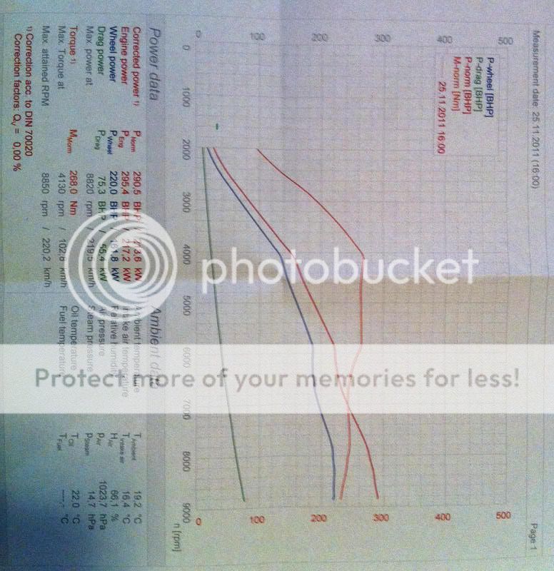
As you can see, the tune is actually pretty good with vtec at 6000, but the stock cams could make more power than the vtec cams in the 6000-7000 area so if i am able to set vtec to 7000, i would get a pretty neat powerband at that area!
The basis thread i found on modifying the ultimate:
https://www.s2ki.com/s2000/topic/635...nage-ultimate/
A quote:
You need to wire the VTM outout from EMU to the ecu.
1. Cut the VTM wire going to ECU ant tape the oil sensor side of it
2. Wire the VTM Output pin of EMU to the VTM pin of ECU
3. Set jumper 17 to "1-2"

After pmíng a guy about this and asking some question about it i seemd to come to the conslusion this is what needed to be done:
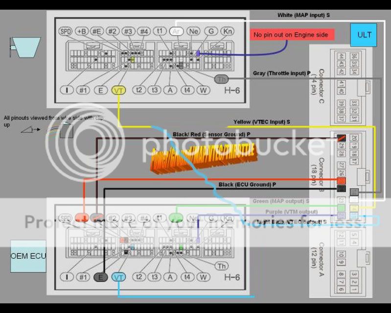
1: 1 need to CREATE a new connection between EMU B21 and ECU C12 ( purple line in picture )
2: redirect EMU B13 to engine harnass B12 ( blue line going to yellow line )
3: OPEN UP the emanage to set jumper 17 to 1-2 ( i need to place a jumper on those 2 pins? )
as per today, i had nobody to chime in on this...
HELP!!
here is my scenario:
Greddy turboéd at 7-8ish psi
As you can see, the tune is actually pretty good with vtec at 6000, but the stock cams could make more power than the vtec cams in the 6000-7000 area so if i am able to set vtec to 7000, i would get a pretty neat powerband at that area!
The basis thread i found on modifying the ultimate:
https://www.s2ki.com/s2000/topic/635...nage-ultimate/
A quote:
You need to wire the VTM outout from EMU to the ecu.
1. Cut the VTM wire going to ECU ant tape the oil sensor side of it
2. Wire the VTM Output pin of EMU to the VTM pin of ECU
3. Set jumper 17 to "1-2"
After pmíng a guy about this and asking some question about it i seemd to come to the conslusion this is what needed to be done:
1: 1 need to CREATE a new connection between EMU B21 and ECU C12 ( purple line in picture )
2: redirect EMU B13 to engine harnass B12 ( blue line going to yellow line )
3: OPEN UP the emanage to set jumper 17 to 1-2 ( i need to place a jumper on those 2 pins? )
as per today, i had nobody to chime in on this...
HELP!!
01-08-2012, 02:46 PM
#3
Registered User
Thread Starter
Join Date: Jan 2008
Location: Oxford
Posts: 997
Likes: 0
Received 0 Likes
on
0 Posts
Now does 1-2 mean both pins connected? Retarded Q but need 100%
I am hating it that the power dies at vtec. Up till 6 is fab, after it's disheartening.
I am hating it that the power dies at vtec. Up till 6 is fab, after it's disheartening.
01-10-2012, 04:02 AM
#4
Registered User
Join Date: Jul 2006
Location: The Netherlands
Posts: 1,008
Likes: 0
Received 0 Likes
on
0 Posts
Where are the EMU/electric guru's? I'm even willing to paypal a small fee for someone who can give me a GOOD step-by-step explanation on what to do!
HELP US OUT!
HELP US OUT!
 01-10-2012, 08:45 AM
#6
Registered User
Join Date: Jul 2006
Location: The Netherlands
Posts: 1,008
Likes: 0
Received 0 Likes
on
0 Posts
Well, soldering wires and that sorta things are a walk in the park for me if i know what's needed to do..
So i really like to save 200 bucks (and excessive int shipping ) if im able to do it myself.
But thx for thinking. I might consider it if no one can help us out..
So i really like to save 200 bucks (and excessive int shipping ) if im able to do it myself.
But thx for thinking. I might consider it if no one can help us out..
01-10-2012, 09:01 AM
#7
I have just bought a new PC and I am in the process of copying over my files, i know for sure i took a photos of the wires specifically for vtec engagement as i have my dropped my engagement and tuned the car myself so it must be correct.
If i do indeed have them i will post them up.
I have one in my gallery but may not be of any use (below), however you definitely need to severe/disconnect one wire i remember that for sure. GEMU harnesses from greddy were never wired up correctly whilst boomslang etc were.
All i have ATM

If i do indeed have them i will post them up.
I have one in my gallery but may not be of any use (below), however you definitely need to severe/disconnect one wire i remember that for sure. GEMU harnesses from greddy were never wired up correctly whilst boomslang etc were.
All i have ATM
Trending Topics
01-10-2012, 09:35 AM
#8


Pry that pin out of the harness, it takes a little coaxing, make sure not to pull the wire out of the pin, then the pin will push into the other connector location. Brad and I did this modification together, but he was the one deciphering the diagram so I'm not 100% on which wires get cut and which one gets transferred over without some refreshing of my own. I know we opened up the emanage and checked some things, one of which was the Voltage outputs to the coils (make sure these are NOT on the 12v selection, but the lower voltage, or you will burn out your coils sooner) 12V is not needed to get full spark ign, the coils determine this, not the emanage signal output.
01-10-2012, 01:20 PM
#9
Registered User
Join Date: Jul 2006
Location: The Netherlands
Posts: 1,008
Likes: 0
Received 0 Likes
on
0 Posts
Fantastic posts guys! THANKS ALOT!!!!!!
Last time i checked ( 99% sure ) i had NO wire going to C pin 10 ( upper right on BLUE connector ) on my harness! So i can "cut" that wire because it aint there!
I also had NO wire coming out of ULT B pin 21....
If i get this straight, i need to make a connection from the "currently empty" ULT B pin 21 going to the BLUE engine connector C pin 10 exactly like YOUR image..
BUT, but, yes there is a but! If you look at the following diagram:
You notice that the wire coming from ULT pin21 is NOT going to the above engine connector pin 10, BUT it goes to the ECU C pin 10..
I know that the ECU pin 10 is connected to engine C pin 10 so i THINK you can connect the ULT B pin21 to either the ECU C pin 10 OR the engine C pin 10
Am i right?
Next problem is that i did not see a metal "pin" inside ULT B 21, so how can i connect a wire between 2 points without 2 "pins" ? I might overlooked though..
01-10-2012, 02:22 PM
#10
Registered User
Join Date: Jul 2006
Location: The Netherlands
Posts: 1,008
Likes: 0
Received 0 Likes
on
0 Posts
S2000junkie,
Im not getting your post on the 12v coils thingie. Are you saying that the emu MIGHT be hooked up wrong from the factory regarding the voltage output to the coils? Never heared of this before...
Im not getting your post on the 12v coils thingie. Are you saying that the emu MIGHT be hooked up wrong from the factory regarding the voltage output to the coils? Never heared of this before...