STR Prep - ECU and Tuning Discusson
 08-09-2012, 11:08 AM
#571

Originally Posted by NFRad' timestamp='1344535675' post='21924979
What "play by play"?
...snip...
Anyway, all in good fun Dave, I respect your opinion.
--Rad
...snip...
Anyway, all in good fun Dave, I respect your opinion.
--Rad
I definitely wasn't saying you were doing the play by play but was directed to Josh, so if it came across that way, my apologies.
We all have our own approaches of doing things, I just frequently differ from Josh, so I was just bustin' on him a little.

The net/net of it is.... I think it's great you guys are making big progress on getting to the bottom of this odd bird of an ECU/piggyback, and hope it finally gets squashed. Plus, I appreciate the willingness of sharing the hard work that you guys put into it with the community. IMO, that's what makes S2KI/S2000 owners different than most. Whoever is brains of this operation, will get my business, of course where it is appropriate. They deserve it!
Sorry for the distraction of actually getting work done/figured out.
-Dave
Funny thing is that there is no central "brain" of the thing. PTuning (via all of us) made enormous strides. Brian will explain how he picked up the ball (it was dropped by PTuning.. like a fumble for failure to connect certain dots)... Brian picked up the ball and has been running that mofo for some good yardage.. The objective is to have him explain how everyone here can make their pre-2006 cars operate properly. Of course no one will be completely happy, but that's due to our nature as anal competitors. I would be very surprised if people here are not extremely appreciative because he has figured out (a) harness issues (b) rev limiter issues (largely related to harness), (c) how to operate the rev limiters, (d) how to convert harnesses to function and what the problems have been, (e) a whole lot more. In sum, while there may be people with errant codes here and there (not promising perfection, but the two cars I know that have been completed seem to be running pretty damn well), the result will be what the PTuning thread initially set out to do, but failed to achieve. So there is no single entity. Brian has definitely been a central player, and will continue to be in the STR S2000 community for sure. People from URBN DK to Rad to Tony E to PTuning (Toan) to Rob R, to me, Imran and others (even where we disagreed) have all contributed invaluable elements to figuring this thing out. Brian has the pieces and is going to reveal the final puzzle since it was his cleverness that finally figured it all out as a whole and ran the ball into the end zone. Just give him a little more time.
 08-09-2012, 11:48 AM
#573


Join Date: Jul 2004
Location: Kentucky
Posts: 1,578
Likes: 0
Received 0 Likes
on
0 Posts
Funny thing is that there is no central "brain" of the thing. PTuning (via all of us) made enormous strides. Brian will explain how he picked up the ball (it was dropped by PTuning.. like a fumble for failure to connect certain dots)... Brian picked up the ball and has been running that mofo for some good yardage.. The objective is to have him explain how everyone here can make their pre-2006 cars operate properly. Of course no one will be completely happy, but that's due to our nature as anal competitors. I would be very surprised if people here are not extremely appreciative because he has figured out (a) harness issues (b) rev limiter issues (largely related to harness), (c) how to operate the rev limiters, (d) how to convert harnesses to function and what the problems have been, (e) a whole lot more. In sum, while there may be people with errant codes here and there (not promising perfection, but the two cars I know that have been completed seem to be running pretty damn well), the result will be what the PTuning thread initially set out to do, but failed to achieve. So there is no single entity. Brian has definitely been a central player, and will continue to be in the STR S2000 community for sure. People from URBN DK to Rad to Tony E to PTuning (Toan) to Rob R, to me, Imran and others (even where we disagreed) have all contributed invaluable elements to figuring this thing out. Brian has the pieces and is going to reveal the final puzzle since it was his cleverness that finally figured it all out as a whole and ran the ball into the end zone. Just give him a little more time.
-Dave
08-09-2012, 11:51 AM
#574
Originally Posted by NFRad' timestamp='1344535675' post='21924979
What "play by play"?
...snip...
Anyway, all in good fun Dave, I respect your opinion.
--Rad
...snip...
Anyway, all in good fun Dave, I respect your opinion.
--Rad
I definitely wasn't saying you were doing the play by play but was directed to Josh, so if it came across that way, my apologies.
We all have our own approaches of doing things, I just frequently differ from Josh, so I was just bustin' on him a little.
The net/net of it is.... I think it's great you guys are making big progress on getting to the bottom of this odd bird of an ECU/piggyback, and hope it finally gets squashed. Plus, I appreciate the willingness of sharing the hard work that you guys put into it with the community. IMO, that's what makes S2KI/S2000 owners different than most. Whoever is brains of this operation, will get my business, of course where it is appropriate. They deserve it!
Sorry for the distraction of actually getting work done/figured out.
-Dave
Please, no need to apologize. I sometimes hate the forums for this very reason, things can easily be read differently person to person.
We're all in this for the same common goal, to get a reliable tune using the EMU. And I feel we are very close to that. I just want to concentrate on my driving
 and hopefully soon forget that I even have an EMU in the back of my seat.
  08-09-2012, 11:56 AM
#575
Originally Posted by nlink720' timestamp='1344539288' post='21925181
Funny thing is that there is no central "brain" of the thing. PTuning (via all of us) made enormous strides. Brian will explain how he picked up the ball (it was dropped by PTuning.. like a fumble for failure to connect certain dots)... Brian picked up the ball and has been running that mofo for some good yardage.. The objective is to have him explain how everyone here can make their pre-2006 cars operate properly. Of course no one will be completely happy, but that's due to our nature as anal competitors. I would be very surprised if people here are not extremely appreciative because he has figured out (a) harness issues (b) rev limiter issues (largely related to harness), (c) how to operate the rev limiters, (d) how to convert harnesses to function and what the problems have been, (e) a whole lot more. In sum, while there may be people with errant codes here and there (not promising perfection, but the two cars I know that have been completed seem to be running pretty damn well), the result will be what the PTuning thread initially set out to do, but failed to achieve. So there is no single entity. Brian has definitely been a central player, and will continue to be in the STR S2000 community for sure. People from URBN DK to Rad to Tony E to PTuning (Toan) to Rob R, to me, Imran and others (even where we disagreed) have all contributed invaluable elements to figuring this thing out. Brian has the pieces and is going to reveal the final puzzle since it was his cleverness that finally figured it all out as a whole and ran the ball into the end zone. Just give him a little more time.
-Dave
Curious, the harness that you sent to PTuning is a Greddy or Boomslang harness?
08-09-2012, 12:28 PM
#576
Join Date: Jul 2004
Location: Kentucky
Posts: 1,578
Likes: 0
Received 0 Likes
on
0 Posts
Note... it was modified on top of that and was used on a turbo car. My co-driver did the re-wiring after PTuning did their thing to the harness... but did not do a full check on it... just changed the wires they knew that needed to be change. My co-driver sent me a pic of it where the map signal wires were spliced together and on the end dead legged. He also needed to run a wire in one of the connectors that did not have anything in it. So, it was pretty hosed up, but he was able to re-wire it to work beautifully with my car.
-Dave
08-09-2012, 12:32 PM
#577
Originally Posted by NFRad' timestamp='1344542207' post='21925330
Dave,
Curious, the harness that you sent to PTuning is a Greddy or Boomslang harness?
Curious, the harness that you sent to PTuning is a Greddy or Boomslang harness?
Note... it was modified on top of that and was used on a turbo car. My co-driver did the re-wiring after PTuning did their thing to the harness... but did not do a full check on it... just changed the wires they knew that needed to be change. My co-driver sent me a pic of it where the map signal wires were spliced together and on the end dead legged. He also needed to run a wire in one of the connectors that did not have anything in it. So, it was pretty hosed up, but he was able to re-wire it to work beautifully with my car.
-Dave


 08-09-2012, 01:18 PM
#579
But the piece of information that goes with that wiring modification is that JP17 needs to be open instead of 1-2.
08-10-2012, 07:21 PM
#580
Former Sponsor

Join Date: Aug 2011
Posts: 76
Likes: 0
Received 0 Likes
on
0 Posts
Okay, so I finally pieced this write-up together to try to help prevent others from wasting too much time in simply obtaining functionality out of the Greddy E-Manage Ultimate in STR trim. I know Rad and Noel have hyped this up a bit, so I hope I don’t disappoint... I don’t think I’m providing anything ground breaking here as most of the information is already out there; and some of the secret wiring seems to be coming to surface, but here’s a stab at trying to consolidate the setup all in one post.
So I’ve slowly been prepping my 2004 S2K for STR trim. Coming from Hondata experience, the EMU is definitely far from it. I learned quick that I can’t just plug in and start tuning. There is a lot of info out there about setting up EMU; but for me, it did not seem to be all consolidated, complete, or 100% accurate as I’ve faced many issues with the hundreds of hours spent trying to simply get full functionality out of this unit. I’m still working on a few issues with more advanced tuning of the unit, but I feel I have a lot of valuable information to share at this time to help get your car setup and running EMU quickly to begin tuning and start making power. I’ve also supplied a base map to start with to correspond with all of the settings and wiring I talk about below. Most importantly, with the settings, wiring, and base map used, I’m running a reliable and repeatable rev limiter extension to 8600 RPM using the factory 04 ECU! I’ve dyno tuned and tested two 2004 S2K’s now (mine and Rad’s) that use this function flawlessly. Unfortunately, I have only played with AP2’s, and do not have an AP1 at my disposal to verify or test everything transfers over. Working with Josh lately on his issues, I cannot confidently say that all the same will apply to the AP1… but at least this may be a foundation to start with.
Disclaimer: I’m not claiming to be an expert on this, but I have spent a LOT of time working on it. The below information is simply my opinion on how the EMU should be set up to start tuning. If you disagree with anything; all good, you don’t have to follow… I’m just trying to help those save a lot of time I felt I had wasted…
1. Jumper Settings:
I’ve read, researched, studied, tested, and these are the end result of many hours I have spent:
JP1: OPEN
JP2: OPEN
JP3: OPEN
JP4: OPEN
JP5: OPEN
JP6: OPEN
JP7: 1-2
JP8: 1-2 (I’ve tested 2-3 and both have functioned the same for me, but I have not done long term testing at 2-3 to verify claims of damaging coils on this setting.)
JP9: OPEN
JP10: 2-3
JP11: OPEN
JP12: OPEN
JP13: OPEN (I’m using JP13 in OPEN for Knock Signal Input with a Boomslang harness purchased in their most popular option “Knock Sensor & Intake Air Temp”)
JP14: OPEN (I’m using JP14 in OPEN for Intake Temp Input with a Boomslang harness purchased in their most popular option “Knock Sensor & Intake Air Temp”. It is stated in the manual to use 1-2 in general for pull-up type (temp sensors), but that was not the case for my AP2v1)
JP15: 1-2
JP16: 1-2
JP17: OPEN (I do not agree with Ballistic’s correction to the Jumper Chart for this setting. He corrected this because the EMU English Manual wording says to set to 1-2 for VTM. I am unable to translate the Japanese and confirm for certain, but as another s2ki.com user has mentioned, the EMU Japanese wording says it should be OPEN for VTM. I would believe this to be more likely. The Japanese chart is identical to the US chart. It makes a lot of sense that Greddy (of Japan), simply made an error in the English translation. However, whatever you want to believe, it really doesn’t matter what is right or wrong as I’ve ran BOTH jumper setting and VTEC functions flawlessly in either for me with no codes.)
JP18: OPEN
JP19: 1-2
JP20: 1-2
JP21: 1-2
2. Wiring:
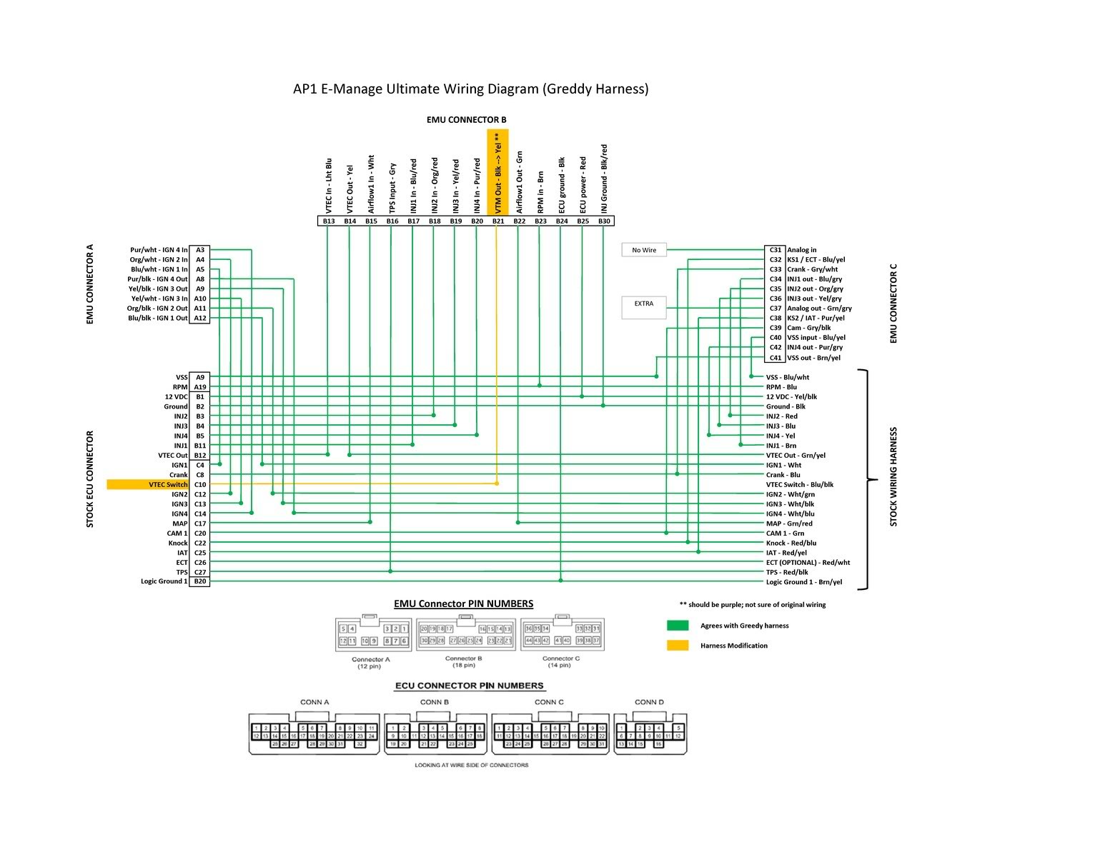
Okay, the Boomslang harness is darn close, but not quite there (at least not one you may have in hand as I am writing this…). All the information online at this point and in the Greddy Manual has wiring that does not work well with our factory NA STR setups. Specifically, the major hindrance preventing the rev limiter extension function from working properly is the wiring for our factory MAP sensor. If using an optional Greddy MAP sensor, the default Boomslang wiring and EMU Manual wiring called out does seem to work correctly based off info from user urban_dK. Since an aftermarket MAP sensor would be illegal in STR trim, we need to perform a wiring change.
Here is a datalog of the issue preventing the rev limit extension from working:
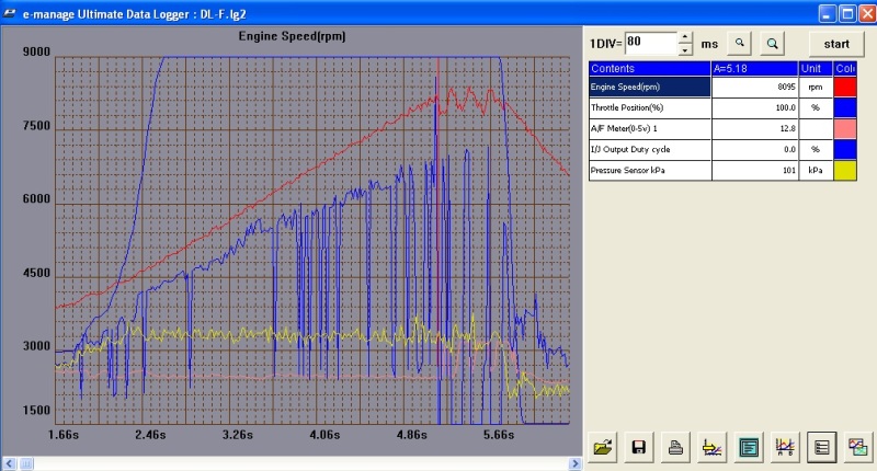
Notice the injector duty cycle fluctuations. From day 1 on my EMU install, I knew this was not right and had a strong feeling if I could figure out how to eliminate what seems to be a total drop in injector signal (specifically at higher rpm), then hopefully the rev limit extension would finally activate… I was able to get the limiter extension to work under these circumstances with V2.23; however, it was (at best) 3% of the time as I did hundreds of slams off rev limiter in my car and only obtained a handful of successful attempts… needless to say; this was very frustrating to see the function working, yet so seldom…
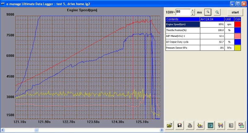
So, after the correction to the MAP sensor wiring; BAM, no more injector fluctuations and I have a consistent 8600rpm limiter!!
The problem:
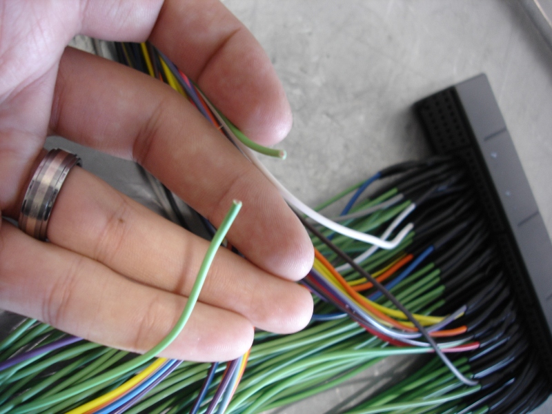
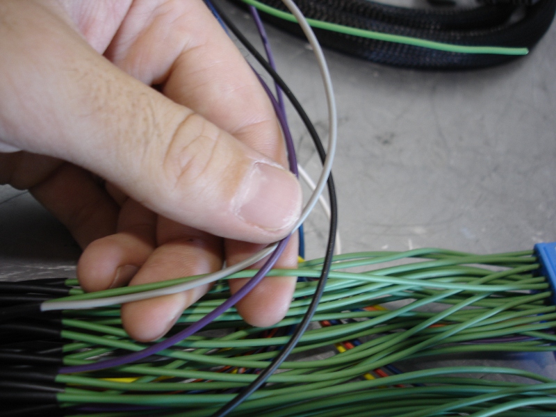
As shown on page 50 of the EMU Installation Manual, Greddy shows wiring to allow the EMU to “intercept” the MAP sensor signal. Basically, the signal coming directly from the MAP sensor (white wire), we are told is to be routed directly to the EMU via Connector B, pin 3. The signal is then filtered through the EMU and is outputted via Connector B, pin 10 (green wire) to the original intended destination, being the ECU. This is useful for boosted applications when desiring to modify the MAP signal output, but offers no functionality for NA applications. And apparently, when our stock MAP sensor is filtered through the EMU in this fashion, it somehow distorts the injector inputs/outputs (for whatever reason, I have no clue).
For NA tuning, all we care about is being able to read the stock MAP sensor, so instead of the recommended MAP “intercept”, we can simply convert the wiring to a MAP “tap”.
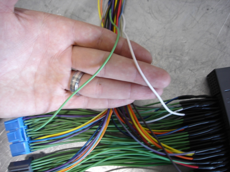
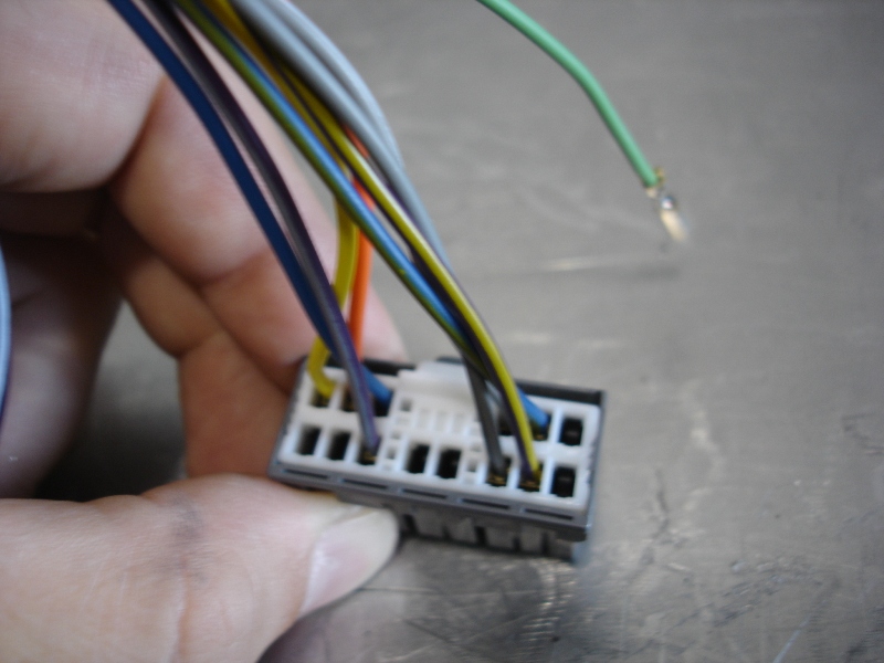
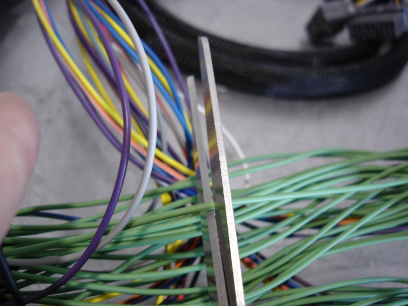
Step 1, cut the green wire as shown:

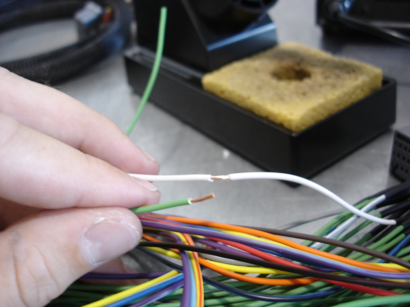
Step 2, strip the wires as shown (the stripped green wire is the portion going into the blue ECU connector):
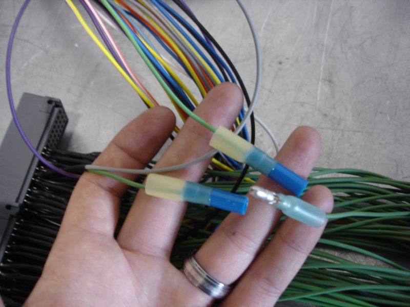
Step 3, soldier and insulate the connection:
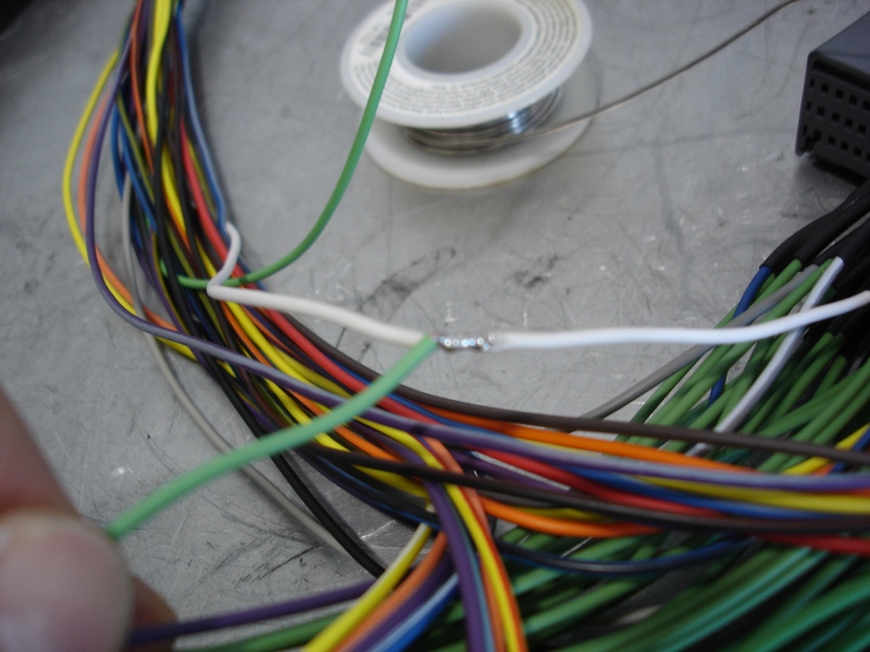
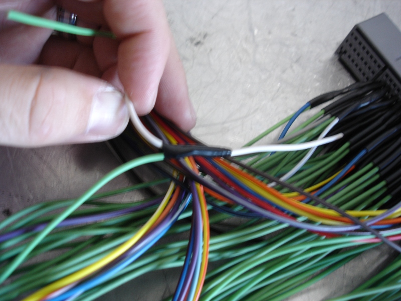
The end result is now a MAP “tap”. The original MAP sensor signal now goes directly into the ECU as it would via the factory wiring and no longer is able to get distorted or whatever is going on when filtered through the EMU. The white wire goes to the EMU to simply allow us to read this “tapped” signal.
As Random1 just stated, I spoke with Boomslang recently as well, where they said future harnesses purchased from them are supplied via customer application. For NA, they said they will provide a MAP tap, and boosted applications they will do the MAP intercept. So the mods above will only be necessary on old Boomslang harnesses, Greddy harnesses, or any harness you need to convert from MAP intercept to MAP tap.
3. Tuning Tips:
When tuning with this piggyback business; I feel there is little point in trying to adjust anything when not in open loop. If you are in closed loop, let the ECU do its thing. You are just fighting the ECU and will be more prone to codes/issues. Being this is not Hondata, we don’t have the luxury of forcing the ECU into open loop at a set MAP signal. This was new to me and took a few datalogs to learn that there are many instances where you can have a high MAP reading (90+kPA), yet if your TPS % is low, our S2K ECU will still be stuck in closed loop and your 90kPA adjustments are just fighting with the ECU in its closed loop status. IMO, it is incorrect to try to tune based off the “Airflow Pressure(V)” or “Absolute Pressure(kPA)” scales within the EMU software UNLESS you know for certain you are in open loop at those cell values. So the question is: “When are we in open loop?” After some playing, I discovered the switch over point on my engine is anytime TPS voltage was over 3.34V (or 73% TPS). These numbers may vary slightly from car to car, but should be similar for all MY04-05.
Attached is a base map for an AP2v1 with a rev limit set to 8500 rpm, ready to start tuning and making power with consistent operation and will be code free, assuming the following:
1. Chassis = 2004-2005 Honda S2000
2. Use of Greddy E-Manage Ultimate using software Version 2.23 and jumper settings specified
3. Use of Boomslang harness purchased with Knock Sensor & Intake Air Temp option + modified to MAP “tap”
To guarantee we are making adjustments to fuel and ignition while in open loop, I have set up the supplied AP2v1 base map with a defining point at 75% where any cell lower than 75% you should leave at 0. I’ve inputted a 0.5 adjustment to the injector and ignition maps to show clarity on where adjustments should be made. Sure, you could modify the ignition timing lower than 75% TPS, but just realize the AFR will be at 14.7:1 and the TPS base does not factor in load, so any changes to ignition should take note of these factors (i.e. be conservative). You would also need a dyno with load holding capabilities to really know where to set any part throttle ignition values..
I believe 95% of you will be very happy with this method of tuning (TPS base) where you can make great gains at WOT (or anything over 75% TPS)...
With all of this being said, I’m not quite done… Contradictory to the above settings and statements, I feel the absolute best way to tune the car is via MAP (speed density) base and not TPS (alpha-n) base. But like stated, I would not tune MAP base unless knowing for certain we are in open loop. For this to happen I would like to be in open loop ALL the time (or as early a TPS position as possible). Additionally, to tune this method, the only way to properly tune all load conditions via MAP base is with the use of a proper load holding dyno. I’ve successfully tuned Rad’s engine in full open loop conditions and the car responds so well at part throttle. After having driven an 06+ on Flashpro, I wasn’t going to be content until I built in the same throttle response into our 04’s. I will say, it is debatable how much part throttle tuning is really worth. Under part throttle racing conditions, if you want more power, you can simply depress the throttle more. In NA STR trim, most of the time we are WOT anyway. I’d say the advantage of this part throttle tuning is very slight; however, I cannot deny that it is a luxury I would rather have. It just makes me feel my tune is complete, and you will have more power at all part throttle positions (assuming proper tuning). Unfortunately, as I am typing this, we are still working through some slight issues with full open loop tuning. After 2.5 days on the dyno tuning Rad's car in open loop, not once did a code pop up. But once the car sat idling and was driven at low load/tps conditions, a few CEL’s were thrown. Right now, it seems we can reset the ECU right before a racing event and all will be good for a while, as it seems to take a bit of time for the codes to present themselves. As long as the car is under load, the ECU is happy and is why during all of the dyno testing, never once did a CEL pop up. There is so much still for me to test and try out that I am hopeful I can crack these CEL’s. I’m not going to post a base map for this unless I get these issues sorted, but for those who want to play, this is what you need to do:
This info is already out there, and had been previously supplied by MugenRio. I must say, without this man’s shared info, I would either still be lost or will have had to put another hundred hours scratching my head figuring this stuff out… (Thank you MugenRio!)
So to force into open loop, you must re-wire your harness as shown (image courtesy of MugenRio; default Boomslang is a TPS “tap” and this setup is a TPS “intercept”):
Warning for AP1 owners: At this time, I do not know if you can wire this way without issues… But again, I have never personally played with an AP1, so I could also be wrong in this regard. I just know the primary difference in the Greddy harnesses for AP1 vs AP2 is that AP1’s are wired for TPS “tap” and AP2 calls for TPS “intercept”. Josh’s AP1 was wired this way and his car could barely run until converting back to TPS “tap”…
This re-wiring (TPS intercept) enables usage of the Analog Output Setting map which allows you to modify the TPS voltage signal in order to force the car into open loop. Below is an image from MugenRio where he shows an example using 4.0 volts; but like I found, I only needed 3.34 volts to get into open loop on my engine (It’s seeming this lower open loop engagement voltage is going to be very important for me as the issue I’m facing is the ECU not being happy with a high or abruptly forced TPS signal at low MAP readings.. right now it looks like the lower and smoother voltage transitions into open loop are giving me the most success with engaging open loop as early as possible without codes… again, this is still a work in progress for me as I’m still working to find the earliest possible open loop engagement point that is CEL free…)
So if you have an AP2 as well as an old Boomslang harness and want to wire this up, you are going to notice a problem with Connector C, pin 7 (it looks as though we have no wire to use for the Analog Voltage Output).
However, the MAP tap mod we just performed conveniently offers us a pinned wire to use. This will be the green wire of Connector B, pin 10.
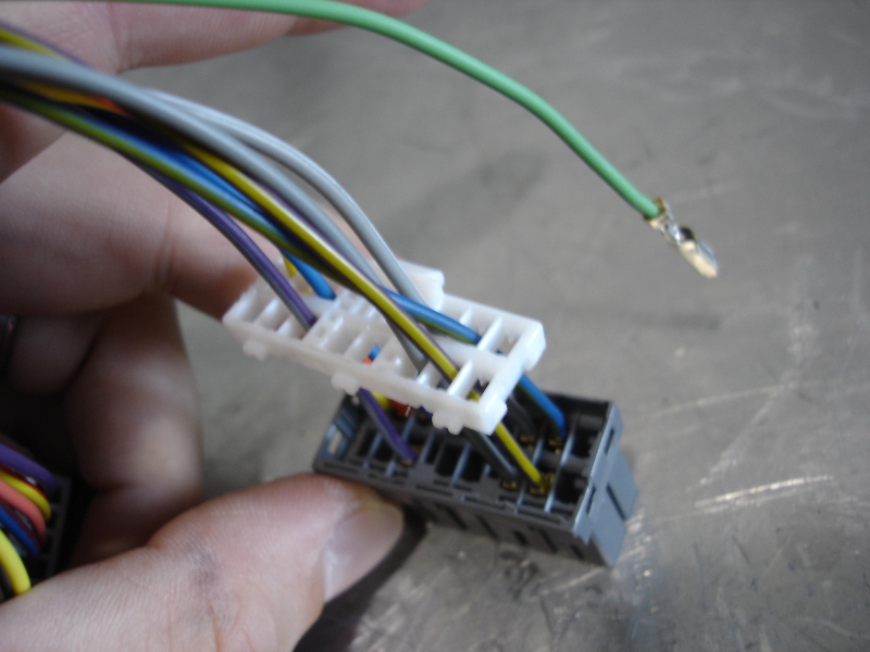
First, pop the white plastic portion of the connector upward as shown:
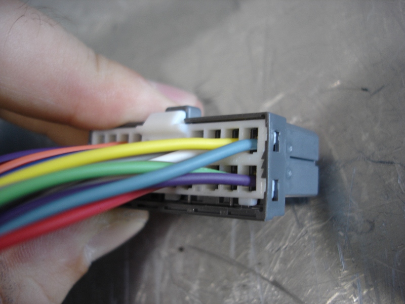
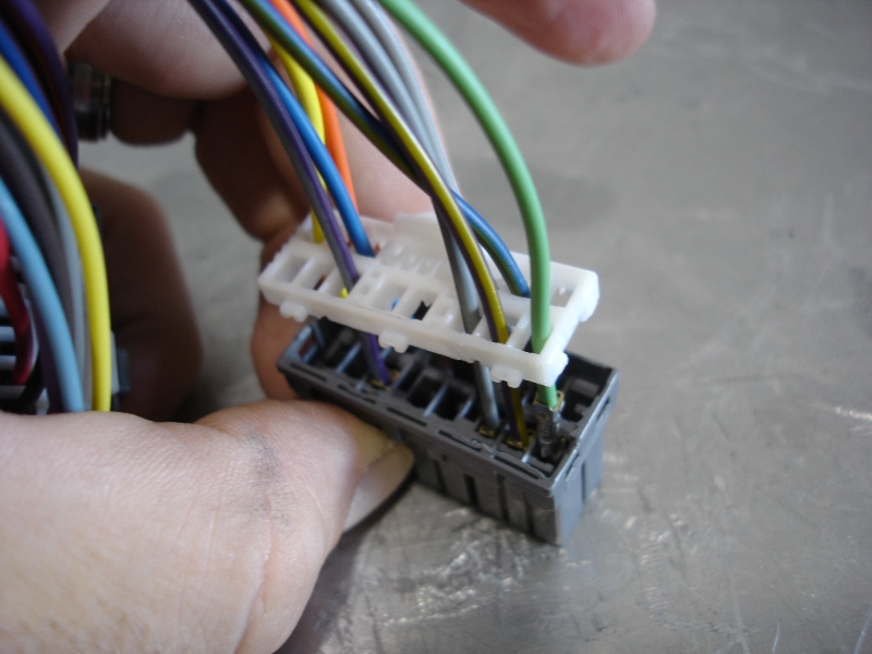
Now you may slide the white portion out of the way:
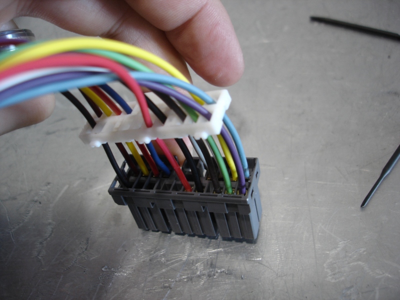
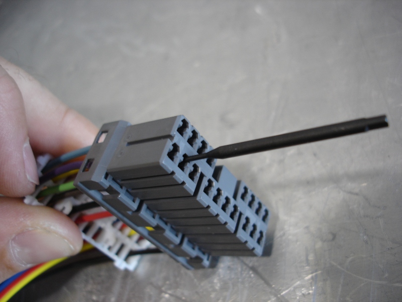
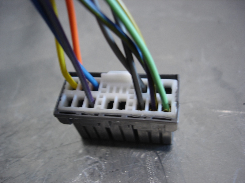
Insert a small flatblade on the other side of the connector and you’ll have to feel around in there, but there is a small plastic tab inside the connector you will need to slightly pry upward. If you pry the tab properly, it releases the connection of the metal pin and you can slide the green wire out (I don’t show in the pic, but you need to pry on internal tab and pull on wire simultaneously):
De-pinned green MAP output wire and connector pieced back together:
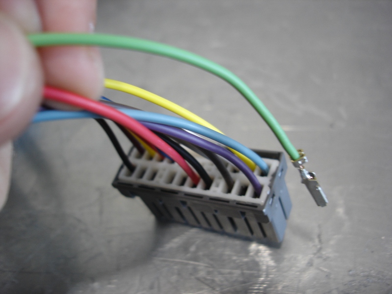
Connector B, ready for the Analog Output wire:
Remove white half of connector:
Simply slide and snap pin into position, much easier than de-pinning process:
Close up connector:
Now locate the gray TPS wire (notice the existing TPS “tap” into the green wire that spans across the harness from engine connector side to ECU connector, allowing the original TPS signal to transfer straight though):
We are now going to cut that green wire, eliminating the TPS signal from directly passing through:
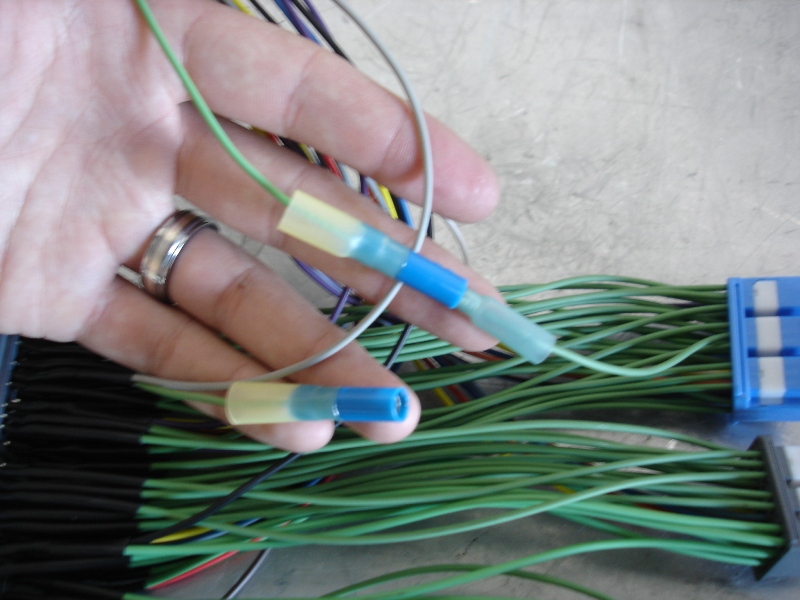
I installed bullet connectors on my harness to be able to play with converting back and forth with this option (green wire coming from EMU connectors is the one we just pinned to the analog output):
This is now the successful TPS “intercept”. The TPS sensor signal (gray wire) is first routed into the EMU, where now we have the option with the Analog Output Setting map to modify the TPS signal, and then it is returned to the ECU via the green wire (originally MAP output wire):
I’ve shown all of these wiring mods, but if purchasing new, you may simply request Boomslang to wire in this fashion to begin with. Either way, hopefully this gives some clarity.
Well, this is all I have for now. If I can figure out CEL free open loop settings for your AP2v1’s, I will be back to share.
I hope this was helpful,
-Brian
(continued on post #626)
So I’ve slowly been prepping my 2004 S2K for STR trim. Coming from Hondata experience, the EMU is definitely far from it. I learned quick that I can’t just plug in and start tuning. There is a lot of info out there about setting up EMU; but for me, it did not seem to be all consolidated, complete, or 100% accurate as I’ve faced many issues with the hundreds of hours spent trying to simply get full functionality out of this unit. I’m still working on a few issues with more advanced tuning of the unit, but I feel I have a lot of valuable information to share at this time to help get your car setup and running EMU quickly to begin tuning and start making power. I’ve also supplied a base map to start with to correspond with all of the settings and wiring I talk about below. Most importantly, with the settings, wiring, and base map used, I’m running a reliable and repeatable rev limiter extension to 8600 RPM using the factory 04 ECU! I’ve dyno tuned and tested two 2004 S2K’s now (mine and Rad’s) that use this function flawlessly. Unfortunately, I have only played with AP2’s, and do not have an AP1 at my disposal to verify or test everything transfers over. Working with Josh lately on his issues, I cannot confidently say that all the same will apply to the AP1…
but at least this may be a foundation to start with.Disclaimer: I’m not claiming to be an expert on this, but I have spent a LOT of time working on it. The below information is simply my opinion on how the EMU should be set up to start tuning. If you disagree with anything; all good, you don’t have to follow… I’m just trying to help those save a lot of time I felt I had wasted…
1. Jumper Settings:
I’ve read, researched, studied, tested, and these are the end result of many hours I have spent:
JP1: OPEN
JP2: OPEN
JP3: OPEN
JP4: OPEN
JP5: OPEN
JP6: OPEN
JP7: 1-2
JP8: 1-2 (I’ve tested 2-3 and both have functioned the same for me, but I have not done long term testing at 2-3 to verify claims of damaging coils on this setting.)
JP9: OPEN
JP10: 2-3
JP11: OPEN
JP12: OPEN
JP13: OPEN (I’m using JP13 in OPEN for Knock Signal Input with a Boomslang harness purchased in their most popular option “Knock Sensor & Intake Air Temp”)
JP14: OPEN (I’m using JP14 in OPEN for Intake Temp Input with a Boomslang harness purchased in their most popular option “Knock Sensor & Intake Air Temp”. It is stated in the manual to use 1-2 in general for pull-up type (temp sensors), but that was not the case for my AP2v1)
JP15: 1-2
JP16: 1-2
JP17: OPEN (I do not agree with Ballistic’s correction to the Jumper Chart for this setting. He corrected this because the EMU English Manual wording says to set to 1-2 for VTM. I am unable to translate the Japanese and confirm for certain, but as another s2ki.com user has mentioned, the EMU Japanese wording says it should be OPEN for VTM. I would believe this to be more likely. The Japanese chart is identical to the US chart. It makes a lot of sense that Greddy (of Japan), simply made an error in the English translation. However, whatever you want to believe, it really doesn’t matter what is right or wrong as I’ve ran BOTH jumper setting and VTEC functions flawlessly in either for me with no codes.)
JP18: OPEN
JP19: 1-2
JP20: 1-2
JP21: 1-2
2. Wiring:
Okay, the Boomslang harness is darn close, but not quite there (at least not one you may have in hand as I am writing this…). All the information online at this point and in the Greddy Manual has wiring that does not work well with our factory NA STR setups. Specifically, the major hindrance preventing the rev limiter extension function from working properly is the wiring for our factory MAP sensor. If using an optional Greddy MAP sensor, the default Boomslang wiring and EMU Manual wiring called out does seem to work correctly based off info from user urban_dK. Since an aftermarket MAP sensor would be illegal in STR trim, we need to perform a wiring change.
Here is a datalog of the issue preventing the rev limit extension from working:
Notice the injector duty cycle fluctuations. From day 1 on my EMU install, I knew this was not right and had a strong feeling if I could figure out how to eliminate what seems to be a total drop in injector signal (specifically at higher rpm), then hopefully the rev limit extension would finally activate… I was able to get the limiter extension to work under these circumstances with V2.23; however, it was (at best) 3% of the time as I did hundreds of slams off rev limiter in my car and only obtained a handful of successful attempts… needless to say; this was very frustrating to see the function working, yet so seldom…
So, after the correction to the MAP sensor wiring; BAM, no more injector fluctuations and I have a consistent 8600rpm limiter!!
The problem:
As shown on page 50 of the EMU Installation Manual, Greddy shows wiring to allow the EMU to “intercept” the MAP sensor signal. Basically, the signal coming directly from the MAP sensor (white wire), we are told is to be routed directly to the EMU via Connector B, pin 3. The signal is then filtered through the EMU and is outputted via Connector B, pin 10 (green wire) to the original intended destination, being the ECU. This is useful for boosted applications when desiring to modify the MAP signal output, but offers no functionality for NA applications. And apparently, when our stock MAP sensor is filtered through the EMU in this fashion, it somehow distorts the injector inputs/outputs (for whatever reason, I have no clue).
For NA tuning, all we care about is being able to read the stock MAP sensor, so instead of the recommended MAP “intercept”, we can simply convert the wiring to a MAP “tap”.
Step 1, cut the green wire as shown:
Step 2, strip the wires as shown (the stripped green wire is the portion going into the blue ECU connector):
Step 3, soldier and insulate the connection:
The end result is now a MAP “tap”. The original MAP sensor signal now goes directly into the ECU as it would via the factory wiring and no longer is able to get distorted or whatever is going on when filtered through the EMU. The white wire goes to the EMU to simply allow us to read this “tapped” signal.
As Random1 just stated, I spoke with Boomslang recently as well, where they said future harnesses purchased from them are supplied via customer application. For NA, they said they will provide a MAP tap, and boosted applications they will do the MAP intercept. So the mods above will only be necessary on old Boomslang harnesses, Greddy harnesses, or any harness you need to convert from MAP intercept to MAP tap.
3. Tuning Tips:
When tuning with this piggyback business; I feel there is little point in trying to adjust anything when not in open loop. If you are in closed loop, let the ECU do its thing. You are just fighting the ECU and will be more prone to codes/issues. Being this is not Hondata, we don’t have the luxury of forcing the ECU into open loop at a set MAP signal. This was new to me and took a few datalogs to learn that there are many instances where you can have a high MAP reading (90+kPA), yet if your TPS % is low, our S2K ECU will still be stuck in closed loop and your 90kPA adjustments are just fighting with the ECU in its closed loop status. IMO, it is incorrect to try to tune based off the “Airflow Pressure(V)” or “Absolute Pressure(kPA)” scales within the EMU software UNLESS you know for certain you are in open loop at those cell values. So the question is: “When are we in open loop?” After some playing, I discovered the switch over point on my engine is anytime TPS voltage was over 3.34V (or 73% TPS). These numbers may vary slightly from car to car, but should be similar for all MY04-05.
Attached is a base map for an AP2v1 with a rev limit set to 8500 rpm, ready to start tuning and making power with consistent operation and will be code free, assuming the following:
1. Chassis = 2004-2005 Honda S2000
2. Use of Greddy E-Manage Ultimate using software Version 2.23 and jumper settings specified
3. Use of Boomslang harness purchased with Knock Sensor & Intake Air Temp option + modified to MAP “tap”
To guarantee we are making adjustments to fuel and ignition while in open loop, I have set up the supplied AP2v1 base map with a defining point at 75% where any cell lower than 75% you should leave at 0. I’ve inputted a 0.5 adjustment to the injector and ignition maps to show clarity on where adjustments should be made. Sure, you could modify the ignition timing lower than 75% TPS, but just realize the AFR will be at 14.7:1 and the TPS base does not factor in load, so any changes to ignition should take note of these factors (i.e. be conservative). You would also need a dyno with load holding capabilities to really know where to set any part throttle ignition values..
I believe 95% of you will be very happy with this method of tuning (TPS base) where you can make great gains at WOT (or anything over 75% TPS)...
With all of this being said, I’m not quite done… Contradictory to the above settings and statements, I feel the absolute best way to tune the car is via MAP (speed density) base and not TPS (alpha-n) base. But like stated, I would not tune MAP base unless knowing for certain we are in open loop. For this to happen I would like to be in open loop ALL the time (or as early a TPS position as possible). Additionally, to tune this method, the only way to properly tune all load conditions via MAP base is with the use of a proper load holding dyno. I’ve successfully tuned Rad’s engine in full open loop conditions and the car responds so well at part throttle. After having driven an 06+ on Flashpro, I wasn’t going to be content until I built in the same throttle response into our 04’s. I will say, it is debatable how much part throttle tuning is really worth. Under part throttle racing conditions, if you want more power, you can simply depress the throttle more. In NA STR trim, most of the time we are WOT anyway. I’d say the advantage of this part throttle tuning is very slight; however, I cannot deny that it is a luxury I would rather have. It just makes me feel my tune is complete, and you will have more power at all part throttle positions (assuming proper tuning). Unfortunately, as I am typing this, we are still working through some slight issues with full open loop tuning. After 2.5 days on the dyno tuning Rad's car in open loop, not once did a code pop up. But once the car sat idling and was driven at low load/tps conditions, a few CEL’s were thrown. Right now, it seems we can reset the ECU right before a racing event and all will be good for a while, as it seems to take a bit of time for the codes to present themselves. As long as the car is under load, the ECU is happy and is why during all of the dyno testing, never once did a CEL pop up. There is so much still for me to test and try out that I am hopeful I can crack these CEL’s. I’m not going to post a base map for this unless I get these issues sorted, but for those who want to play, this is what you need to do:
This info is already out there, and had been previously supplied by MugenRio. I must say, without this man’s shared info, I would either still be lost or will have had to put another hundred hours scratching my head figuring this stuff out… (Thank you MugenRio!)
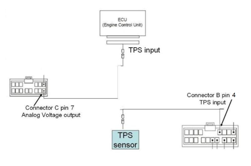
So to force into open loop, you must re-wire your harness as shown (image courtesy of MugenRio; default Boomslang is a TPS “tap” and this setup is a TPS “intercept”):
Warning for AP1 owners: At this time, I do not know if you can wire this way without issues…
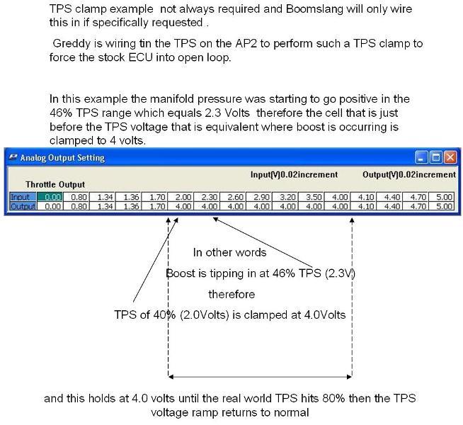
But again, I have never personally played with an AP1, so I could also be wrong in this regard. I just know the primary difference in the Greddy harnesses for AP1 vs AP2 is that AP1’s are wired for TPS “tap” and AP2 calls for TPS “intercept”. Josh’s AP1 was wired this way and his car could barely run until converting back to TPS “tap”…This re-wiring (TPS intercept) enables usage of the Analog Output Setting map which allows you to modify the TPS voltage signal in order to force the car into open loop. Below is an image from MugenRio where he shows an example using 4.0 volts; but like I found, I only needed 3.34 volts to get into open loop on my engine (It’s seeming this lower open loop engagement voltage is going to be very important for me as the issue I’m facing is the ECU not being happy with a high or abruptly forced TPS signal at low MAP readings.. right now it looks like the lower and smoother voltage transitions into open loop are giving me the most success with engaging open loop as early as possible without codes… again, this is still a work in progress for me as I’m still working to find the earliest possible open loop engagement point that is CEL free…)
So if you have an AP2 as well as an old Boomslang harness and want to wire this up, you are going to notice a problem with Connector C, pin 7 (it looks as though we have no wire to use for the Analog Voltage Output).
However, the MAP tap mod we just performed conveniently offers us a pinned wire to use. This will be the green wire of Connector B, pin 10.
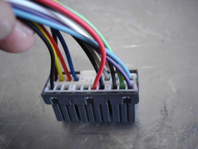
First, pop the white plastic portion of the connector upward as shown:
Now you may slide the white portion out of the way:
Insert a small flatblade on the other side of the connector and you’ll have to feel around in there, but there is a small plastic tab inside the connector you will need to slightly pry upward. If you pry the tab properly, it releases the connection of the metal pin and you can slide the green wire out (I don’t show in the pic, but you need to pry on internal tab and pull on wire simultaneously):
De-pinned green MAP output wire and connector pieced back together:
Connector B, ready for the Analog Output wire:
Remove white half of connector:
Simply slide and snap pin into position, much easier than de-pinning process:
Close up connector:
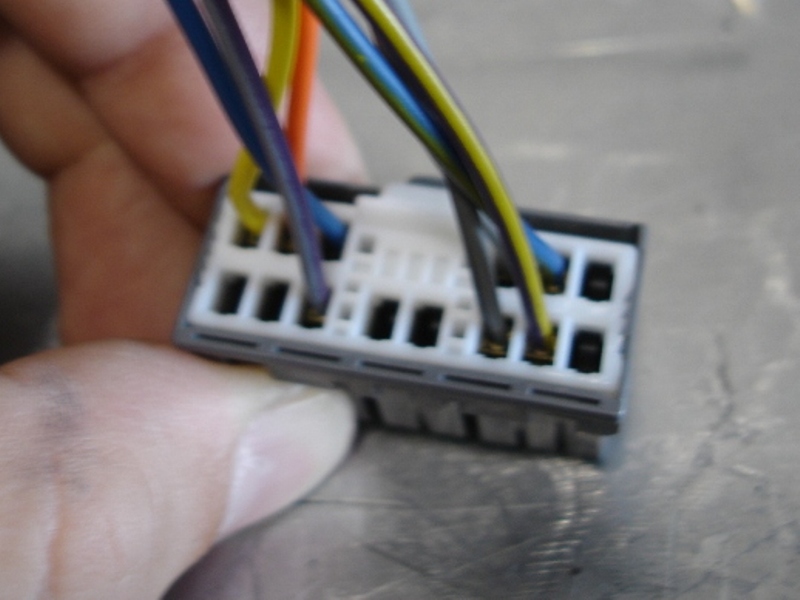
Now locate the gray TPS wire (notice the existing TPS “tap” into the green wire that spans across the harness from engine connector side to ECU connector, allowing the original TPS signal to transfer straight though):
We are now going to cut that green wire, eliminating the TPS signal from directly passing through:
I installed bullet connectors on my harness to be able to play with converting back and forth with this option (green wire coming from EMU connectors is the one we just pinned to the analog output):
This is now the successful TPS “intercept”. The TPS sensor signal (gray wire) is first routed into the EMU, where now we have the option with the Analog Output Setting map to modify the TPS signal, and then it is returned to the ECU via the green wire (originally MAP output wire):
I’ve shown all of these wiring mods, but if purchasing new, you may simply request Boomslang to wire in this fashion to begin with. Either way, hopefully this gives some clarity.
Well, this is all I have for now. If I can figure out CEL free open loop settings for your AP2v1’s, I will be back to share.
I hope this was helpful,
-Brian
(continued on post #626)