
My PLX R500 Wideband install

Thread Starter
Member

Joined: Apr 2004
Posts: 33,838
Likes: 23
From: Sunshine Coast - England UK
Hpefully this is of some use!
Right, got the PLX wideband mostly installed today. I wired in the power and earth to the ECU, then wired in the main signals, Speed and Knock input from the factory sensors, and AFR will go in once the actual wideband sensor is installed. This is on a separate cable, as it replaces the stock narrowband sensor. Didn't have time to fit this today!
I then spliced and soldered in my 4 other chosen signals that I have decided to monitor, which are:
1) MAP volts
2) Throttle pos
3) Coolant temp
4) Air intake temp
Uncovered the ECU on the passenger sidewall
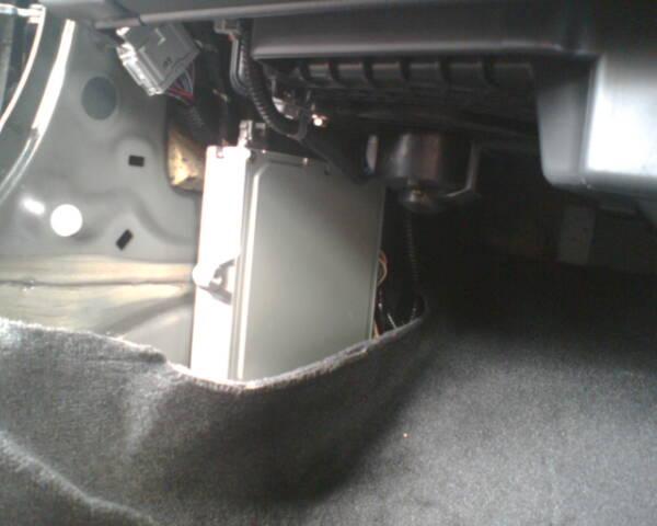
Unbolted the ECU then pulled the 3 connectors

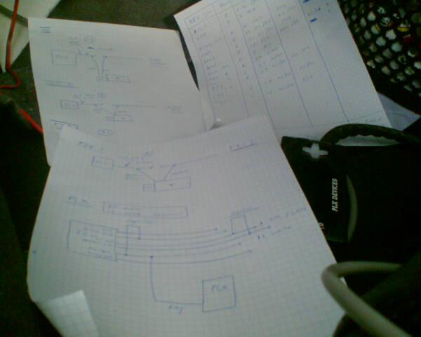
My scruffy homemade wiring notes
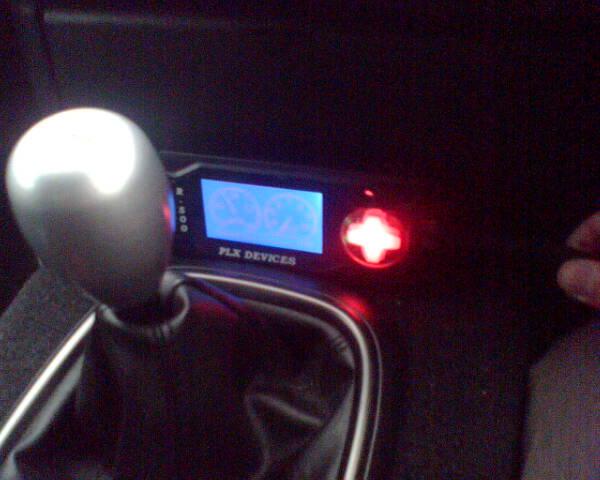
PLX installed and tested!
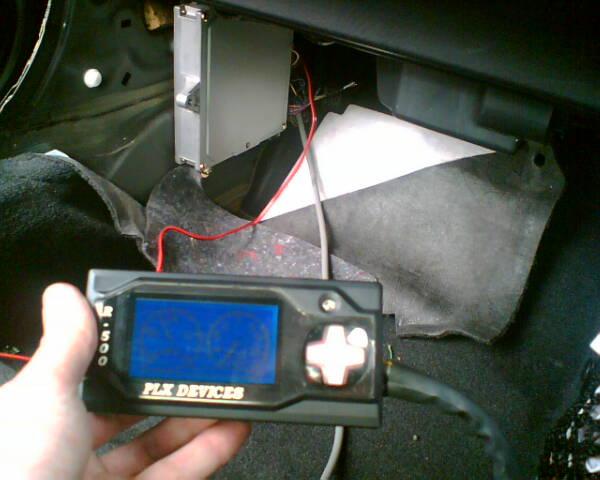
I now have to enter all the calibrations into the PLX, as it needs to know what all the 0-5 volts signals actually mean. For example, the min MAP is 0.32v = -13.9 psi, and max MAP is 4.84v = 10.9 psi and its linear - so enter this into the PLX and away you go!
Got to replace the lambda sensor next...
Basically I got the Wideband lambda probe installed and fitted the resistors that need to make the car run correctly and no CEL's etc. Its worth re-itterating at this point that the wideband is by no means essential, but for me its quite important and its what's been holding up the rest of the S/C install.
Right, first was to find and unbolt the primary lambda sensor. Found it easy enough but the connector plug was a bugger to get undone!
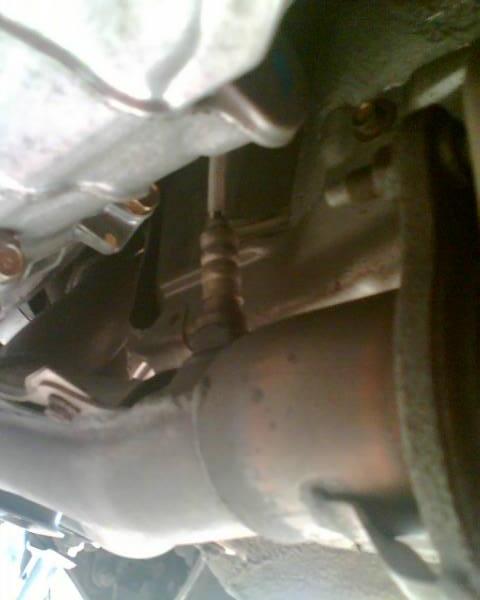
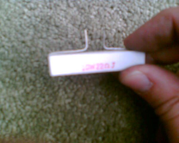
Once disconnected I put the new Wideband in. I also decided to put the 20 ohm 10W resistor into the old lambda plug, that goes back to the ECU. This is needed to stop you getting a CEL, by completing the heater circuit. I modified the resistor a bit You can also do this at the ECU which might be easier.
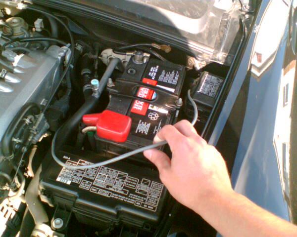
Once installed I ran the new wideband lead up through the engine bay (choosing a nice safe route)
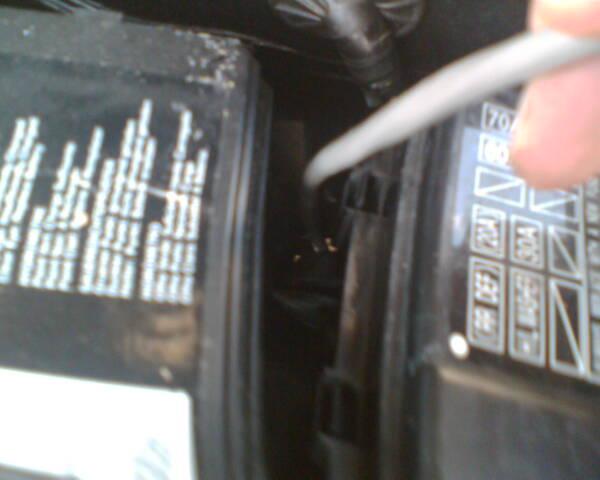
Then threaded the connector through the bulkhead. You can just about see it in this pic and its the hole where all the ECU wires go through.
Pic of the wideband unit in its new home!
Such a good bit of kit.
Did some logging sessions to record the AFR and Knock so will post these up when ive saved them to JPEG. I can then see how the car is running compared to when the S/C is on
The car actually feels much smoother now, with the simulated output from the wideband going into the ECU, instead of the old sensor. Bonus!
MB
Right, got the PLX wideband mostly installed today. I wired in the power and earth to the ECU, then wired in the main signals, Speed and Knock input from the factory sensors, and AFR will go in once the actual wideband sensor is installed. This is on a separate cable, as it replaces the stock narrowband sensor. Didn't have time to fit this today!
I then spliced and soldered in my 4 other chosen signals that I have decided to monitor, which are:
1) MAP volts
2) Throttle pos
3) Coolant temp
4) Air intake temp
Uncovered the ECU on the passenger sidewall
Unbolted the ECU then pulled the 3 connectors
My scruffy homemade wiring notes
PLX installed and tested!
I now have to enter all the calibrations into the PLX, as it needs to know what all the 0-5 volts signals actually mean. For example, the min MAP is 0.32v = -13.9 psi, and max MAP is 4.84v = 10.9 psi and its linear - so enter this into the PLX and away you go!
Got to replace the lambda sensor next...
Basically I got the Wideband lambda probe installed and fitted the resistors that need to make the car run correctly and no CEL's etc. Its worth re-itterating at this point that the wideband is by no means essential, but for me its quite important and its what's been holding up the rest of the S/C install.
Right, first was to find and unbolt the primary lambda sensor. Found it easy enough but the connector plug was a bugger to get undone!
Once disconnected I put the new Wideband in. I also decided to put the 20 ohm 10W resistor into the old lambda plug, that goes back to the ECU. This is needed to stop you getting a CEL, by completing the heater circuit. I modified the resistor a bit
You can also do this at the ECU which might be easier. Once installed I ran the new wideband lead up through the engine bay (choosing a nice safe route)
Then threaded the connector through the bulkhead. You can just about see it in this pic and its the hole where all the ECU wires go through.
Pic of the wideband unit in its new home!
Such a good bit of kit.
Did some logging sessions to record the AFR and Knock so will post these up when ive saved them to JPEG. I can then see how the car is running compared to when the S/C is on
The car actually feels much smoother now, with the simulated output from the wideband going into the ECU, instead of the old sensor. Bonus!
MB

Thread Starter
Member
Joined: Apr 2004
Posts: 33,838
Likes: 23
From: Sunshine Coast - England UK
Hi Mark
The two main dials are fixed as AFR and EGT.
The bar below can be configured to any of the analog inputs, ie knock / boost etc.
Shame the EGT can be replaced with something else though. AFR and knock are my main concerns, so as long as I can see these im happy. Also the main function of the box is to be able to log data and then look at it on PC so im quite happy with that.
Been looking at how the knock behaves as standard, and will see what it does with the blower on there
Yours going well?
MB
Thread Starter
Member
Joined: Apr 2004
Posts: 33,838
Likes: 23
From: Sunshine Coast - England UK
PS - im sure the dials will be adjustable at some point, PLX seem to be quite good at firmware upgrades, which can be downloaded from their website, then uploaded to the PLX by cable.
Latest update gives loads more screens.
MB
Latest update gives loads more screens.
MB
Thread Starter
Member
Joined: Apr 2004
Posts: 33,838
Likes: 23
From: Sunshine Coast - England UK
Hi Trip,
You need to connect the 20 ohm 10W resistor across the heater + and heater - signals. You can do this at the ECU / C101 connector or you can do it at the now disconnected lambda sensor plug.
I did it at the plug as its easy to get to and wont get hot. Its the 2 white wire pins in the connector that you want to connect.
Even better would be to get a spare lambda sensor plug to attach to the plug on the car and pre wire that with the resistor.
MB
Trending Topics
Thread Starter
Member
Joined: Apr 2004
Posts: 33,838
Likes: 23
From: Sunshine Coast - England UK
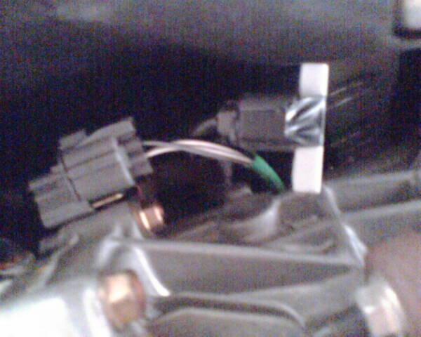
If you look at the 3rd pic, the plug has been disconnected and you can see where ive put the resistor. You can also see the secondary lambda plug with the green cable. The 2 white wires on that are the heater +/- for the secondary sensor.
MB
MB


Joined: May 2004
Posts: 1,245
Likes: 0
Originally Posted by Dark Blue Mark,Oct 18 2005, 11:12 PM
Even better would be to get a spare lambda sensor plug to attach to the plug on the car and pre wire that with the resistor.
MB
MB
Is that electrical tape holding the resistor in place ? the glue on the tape will heat up and eventually the tape will loose its power to hold in place.
Thread Starter
Member
Joined: Apr 2004
Posts: 33,838
Likes: 23
From: Sunshine Coast - England UK
Agreed on using a bad / old sensor.
It is elec tape, but that was temporary while I secured it with some adhesive Good spot!
It wont come off too easily now and ive secured it in an upright position.
MB
It is elec tape, but that was temporary while I secured it with some adhesive
Good spot!It wont come off too easily now and ive secured it in an upright position.
MB