When you click on links to various merchants on this site and make a purchase, this can result in this site earning a commission. Affiliate programs and affiliations include, but are not limited to, the eBay Partner Network.
Zdan, yes, you're correct, thanks. I should have said that the "elastic component of sprung-weight transfer" depends on this height distance. In fact, the relevant CG height for this calculation is that of the sprung mass only.
There is also a "geometric component of sprung-weight transfer", which depends on the roll center heights relative to the F/R weight distribution; and finally there is unsprung-weight transfer, which basically only depends on the amount of unsprung weight and the axle heights.
For a given lateral acceleration, the three components will indeed add up to total weight * CG height * lat accel / track. (Here the CG is that of the overall vehicle, not just the sprung weight.)
Thinking more...
As roll centers get lower, the elastic weight trasfer increases, but the geometric transfer decreases, and can even be negative (i.e. weight jacking)! Assuming our car's centers are very low to begin with, this might mean that lowering the car moderately doesn't have much effect at all on sprung weight transfer. It'll all depend on the exact shape of the curves, of course.
I found some more information...feel free to comment...it's been a long day at work and I didn't really read it myself:
"About correction of Roll center"-----
Drivers tend to consider that center of gravity would be lowered and have more stability if car height is lowered. However, if you are using the normal arm, the arms would be raised and opened up outwards and the center of gravity of car and roll center would be apart . And the roll amount unnecessarily increases while the suspension stroke decreases, and causes the condition of " Grip limitation between tire and ground surface will be lowered".
By using Ikeya formula's "Front lower arm", "Rear lower arm" and "Tie-rod end" which possess the roll center adjuster function will correct the roll center and set back to the position where has the shorter distance between center of gravity and roll center and then decreases the roll amount
Additionally, we would like to recommend to install both Front and Rear at the same time. Because the roll center of Front and Rear would be "shifted", if mounting only on Front side, and the roll axis will be shifted on Front and the roll amount changes on Rear, and causes loss of the stability in the car behavior.
From these points, we would like to recommend to wear both on Front and Rear.
The cross-point on the extension of mounting position of suspension arm and tread centerline is instantaneous rotation center of contact point to ground of the tire. Car inclines (roll) with this point as a center.
Roll center is lowered if car height is lowered with normal arms mounted. Even with the same roll angle, cornering performance would be decreased because of large distance from the rotation center which causes bigger movement.
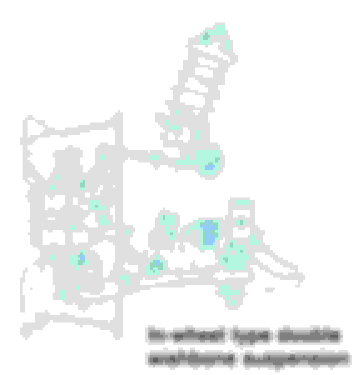
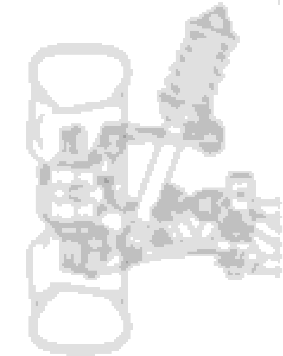
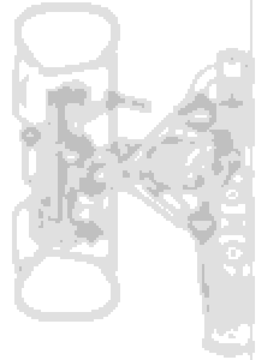
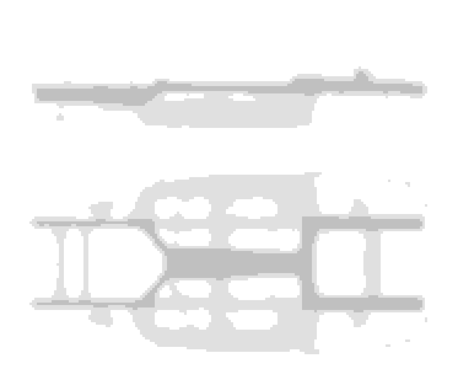
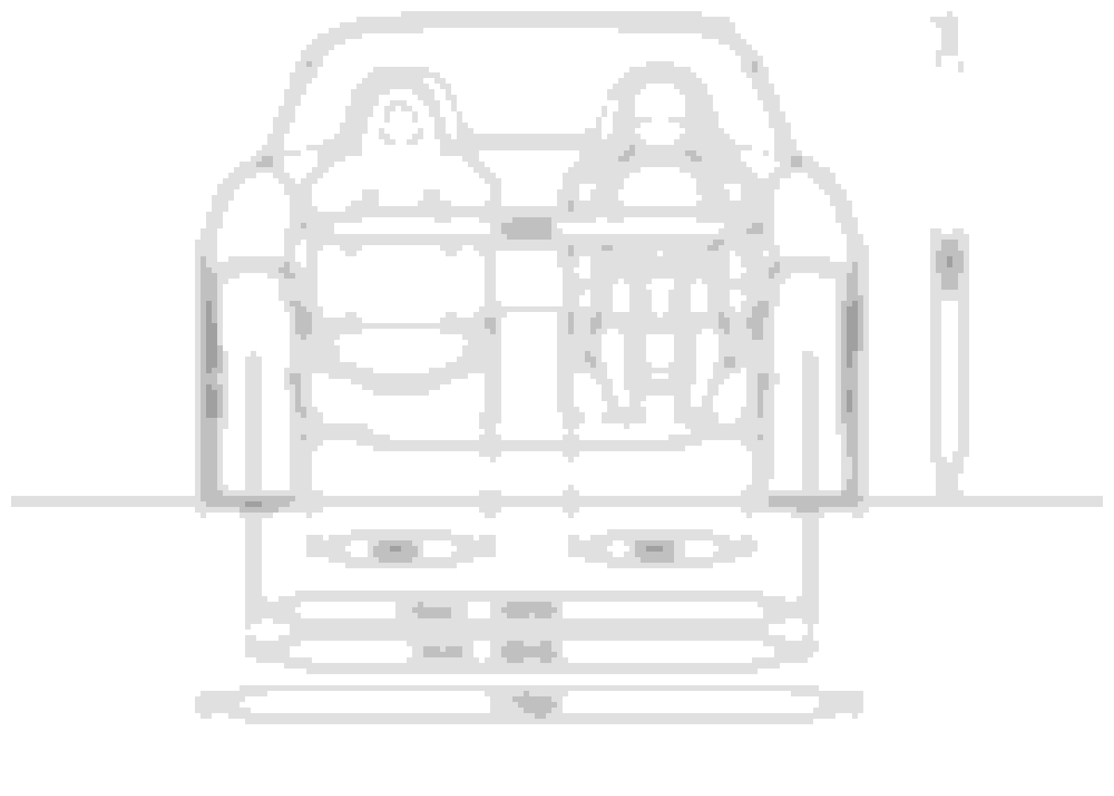
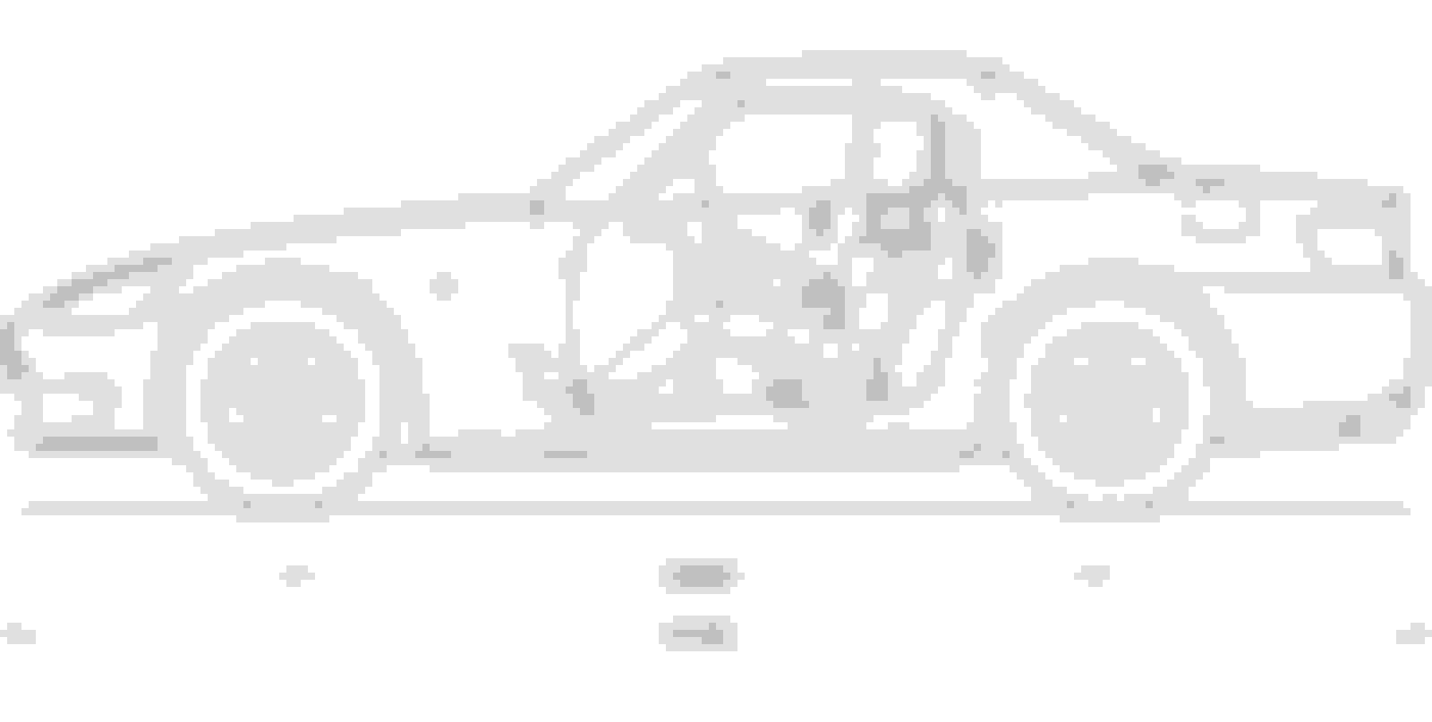
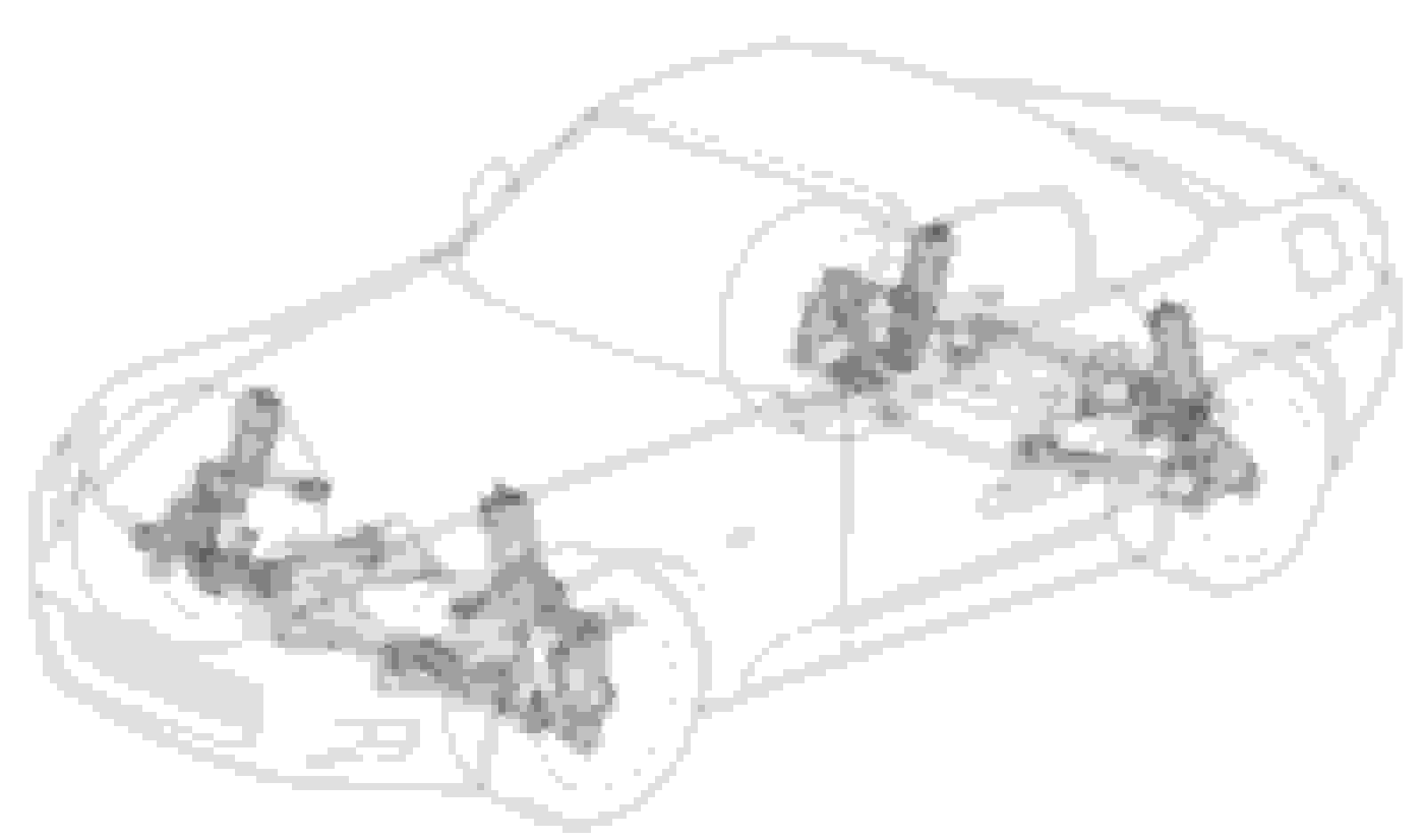
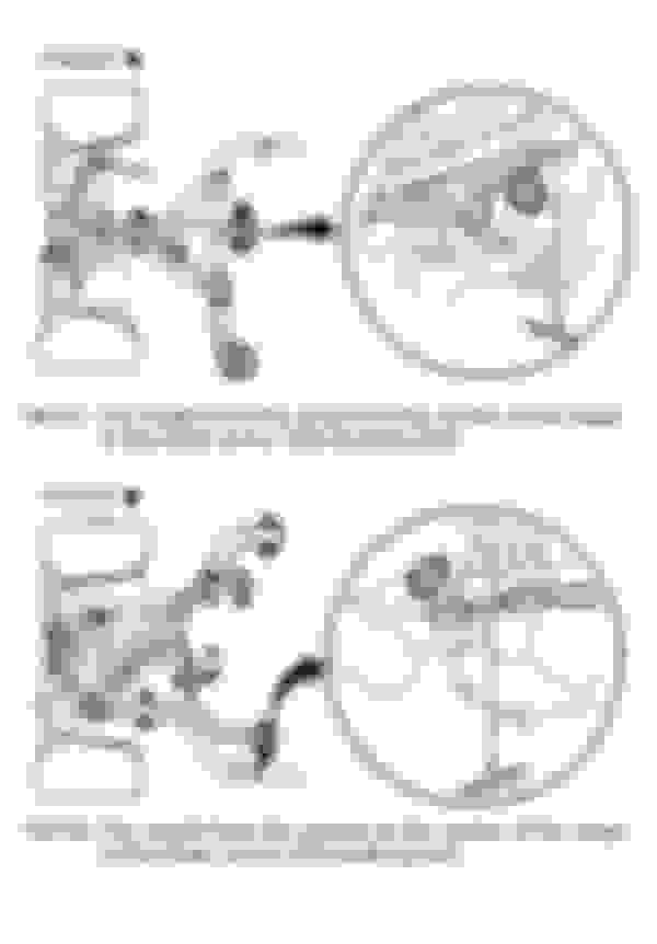
P.S. Here's some more hi-res schematics of suspension and body (all AP1). None of them have every dimension and relation you need, but combined they might get you there.
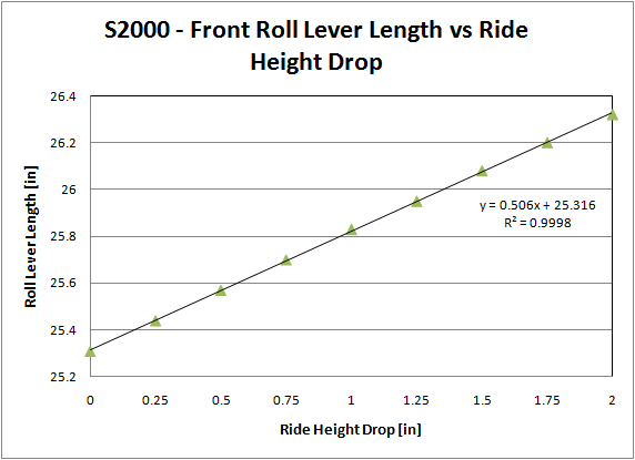
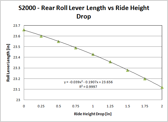
Had a chance to update my initial estimate using the corrected track width numbers. It changed the rate of change in the roll lever length from 0.3 in/in to 0.5 in/in. Those units are inches of roll lever length increase per inch of ride height decrease. I also made a similar model for the rear suspension. The rear suspension image is clipped on the left-hand side, so the "guess" factor for the rear is a bit higher than the front.
Surprisingly, the rear roll lever decreases in length as you drop the chassis and the relationship isn't quite linear.
Again, these are **just estimates** based on the images above. The rear is kinda tricky because of the angle of the lower control arm, which is tough to capture in a 2D model of the geometry. This will all be improved upon the actual suspension points are measured in 3D space. Just kinda cool to investigate at this point...
What were the front and rear roll center heights that you found (at stock ride height)?
Can you infer the 3D positions of the suspension mounting points from the horizontal & vertical views?
Here's one showing the subframes; it's an iso view, but might (or might not) help guide you as far as locating the subframe attachment points to, and offsets from, the chassis frame, and from there the suspensiom arm attachment points in 3D space.
And an iso of the subframe:
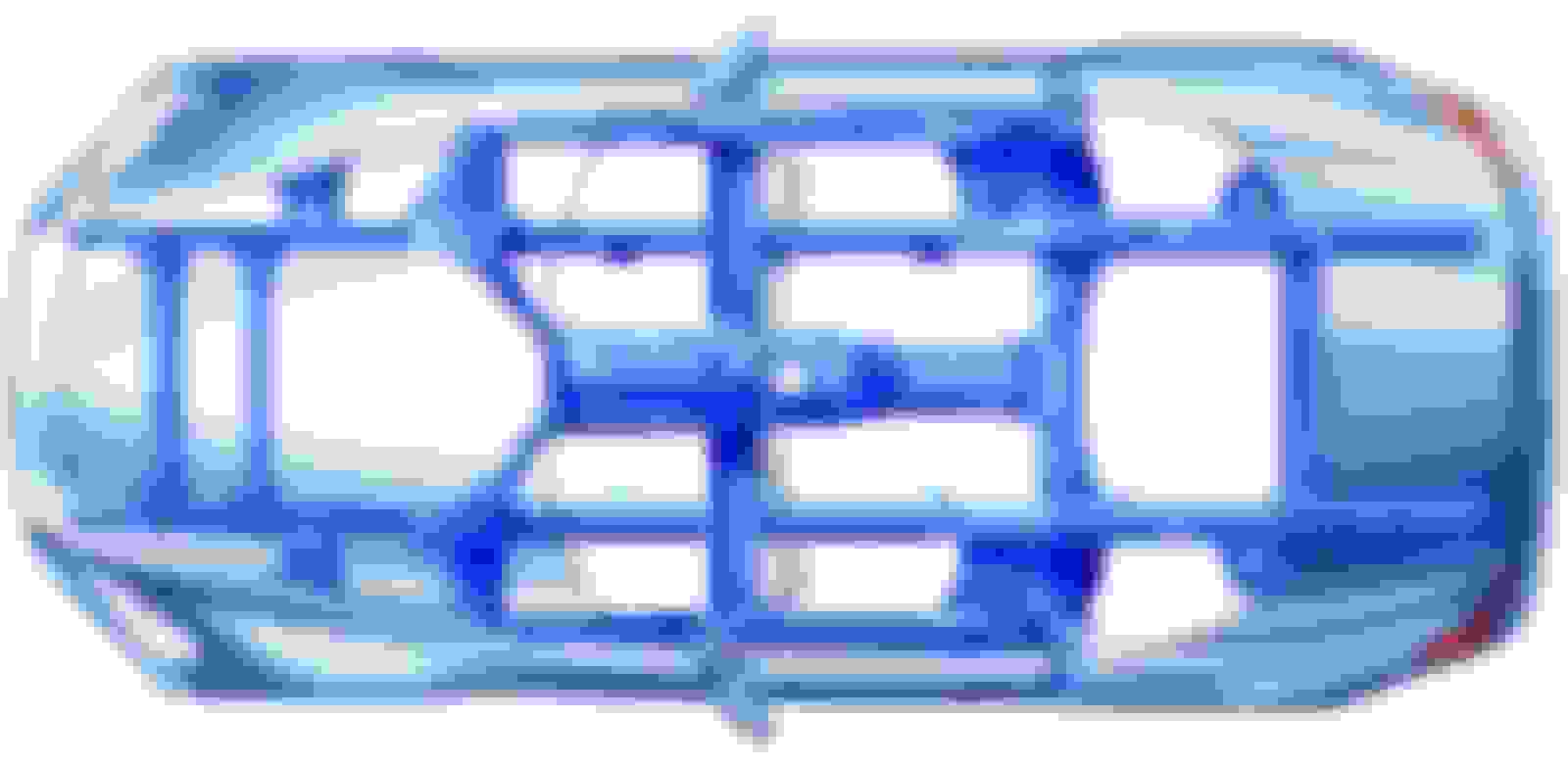
Oh, and here's a low-res one (from the Helm manual) with a top view of the rear susp; should help you check out your rear arm locations.
What were the front and rear roll center heights that you found (at stock ride height)?
Can you infer the 3D positions of the suspension mounting points from the horizontal & vertical views?
You can figure out the roll center height for different drops by taking the assumed stock CG height (26.5") and subtracting the roll lever length from the graph. So, for stock ride height, you get the following:
Front: 1.2"
Rear: 2.8"
Having used the images as a starting point, I think it would be more value added to start taking actual measurements vs. trying to work with ISO images. Just seems like there would be a high potential for error. It'll be interesting to see how close the above estimates compare to the values based on actual measurements.
26.5" seems WAY high for c.g. height, most of the major masses are ENTIRELY below that! Gotta be more like 22", maybe 20".
I've used that method for calculating c.g. heights of motorcycles/scooters, and I was never able to get precise or repeatable values.
Not saying others can't get good results, but there's just no freaking WAY the c.g. is at 26.5"!

 02-03-2011, 02:53 PM