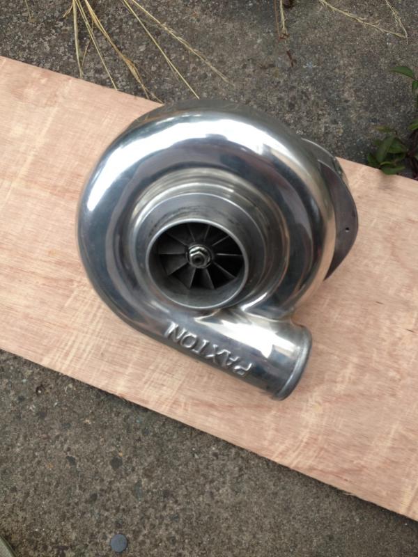
How I rebuilt my Paxton Novi 1000
 12-03-2014, 04:30 AM
#1

Thread Starter
I promised a couple of members on the board that I would write a summary of how I built my Novi 1000.
This is not a HOW TO! it's simply some pictures and information on how I did mine so please be aware this may not be the correct procedure.
I thought mine sounded loud so I wanted to change the bearings, hence why I rebuilt it.
First I removed the supercharger from the mounting plate:
Removed the pulley and washer:
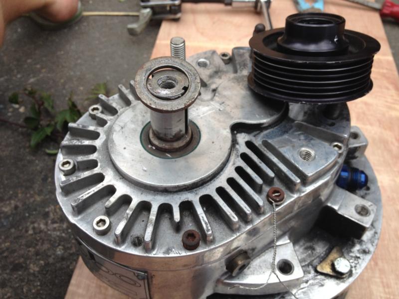
Then I removed all the allen key cap head bolts holding the rear casing on:
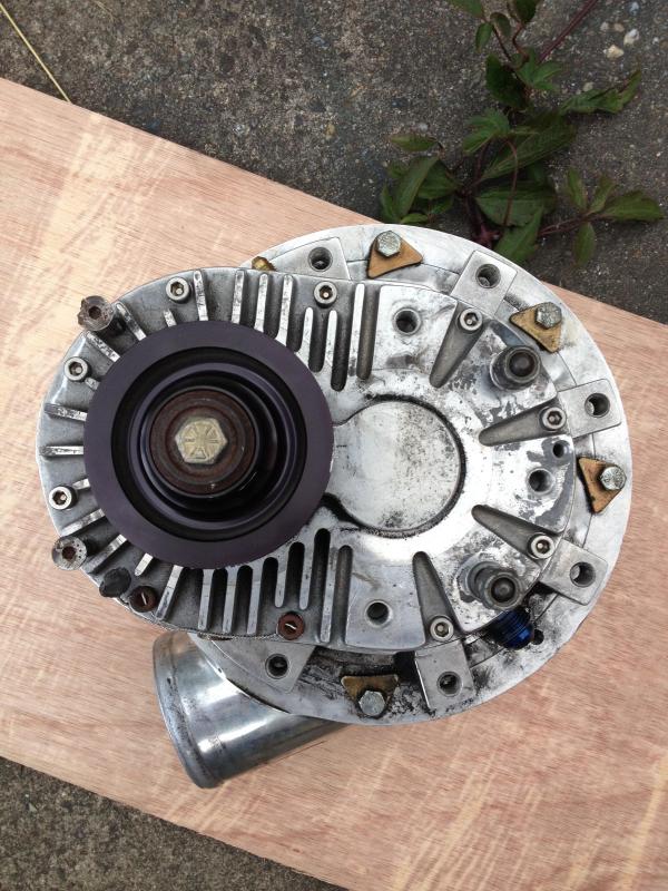
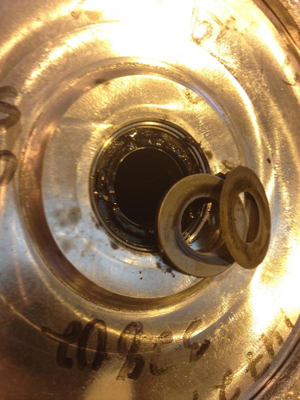
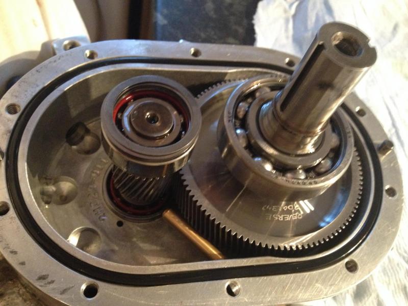
View of inside:
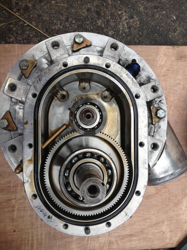
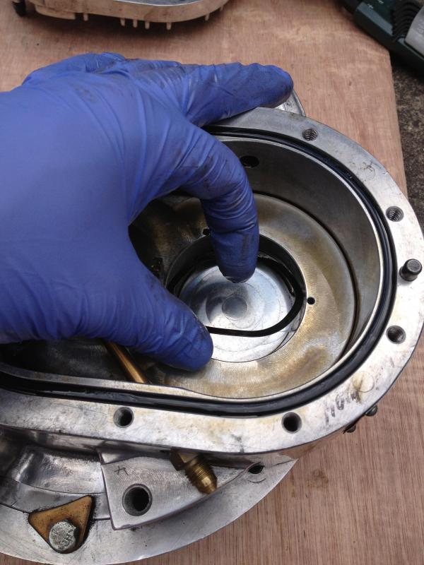
I removed the three spring washers and two spacing washers form the output shaft bearing. I placed these in the insert in the housing plate for safe keeping:
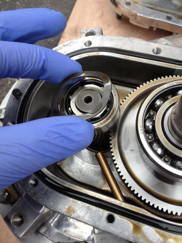
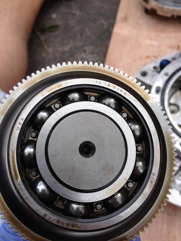
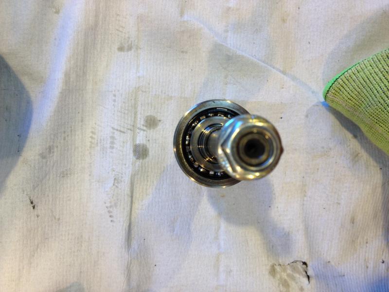
Output shaft bearings:
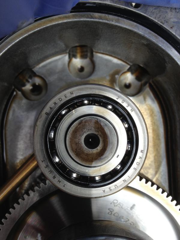
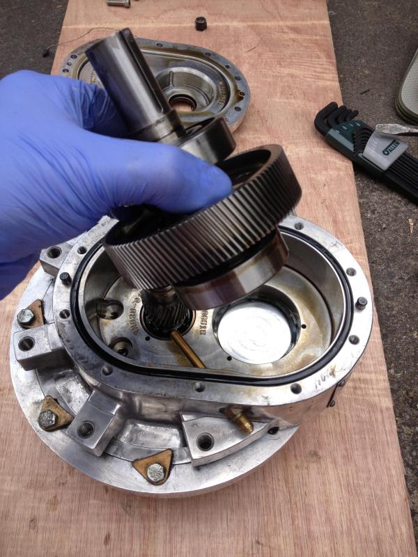
Input shaft bearings:
Then I lifted the input shaft assembly out:
Removed the spring washer and stored it for safe keeping:
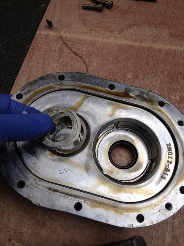
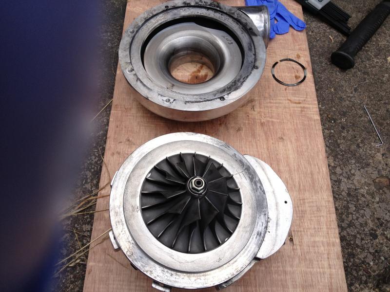
I then flipped the casing over and removed the volute:
This is not a HOW TO! it's simply some pictures and information on how I did mine so please be aware this may not be the correct procedure.
I thought mine sounded loud so I wanted to change the bearings, hence why I rebuilt it.
First I removed the supercharger from the mounting plate:

Removed the pulley and washer:

Then I removed all the allen key cap head bolts holding the rear casing on:

View of inside:

I removed the three spring washers and two spacing washers form the output shaft bearing. I placed these in the insert in the housing plate for safe keeping:


Output shaft bearings:

Input shaft bearings:

Then I lifted the input shaft assembly out:

Removed the spring washer and stored it for safe keeping:

I then flipped the casing over and removed the volute:

 12-03-2014, 04:30 AM
#2
Thread Starter
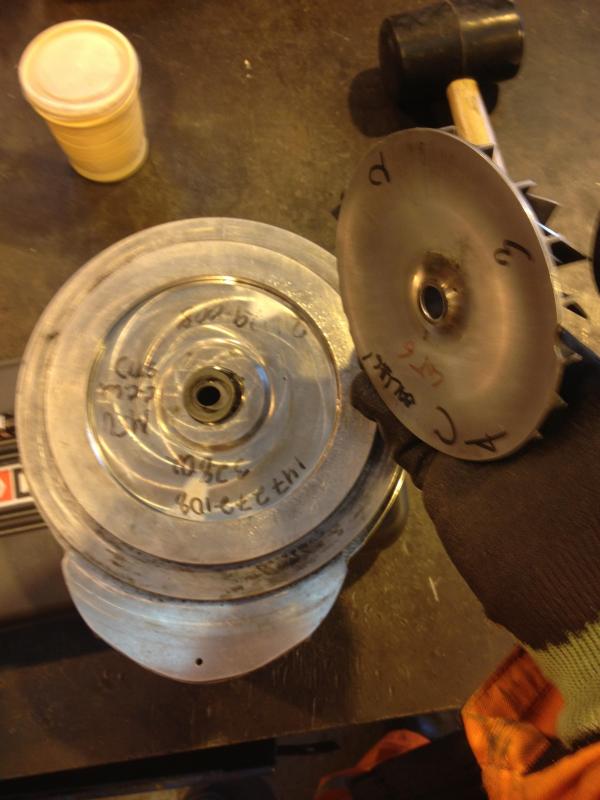
Now off I went to my workshop (well my work's workshop:
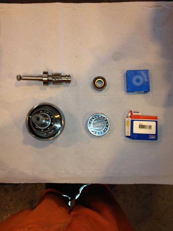
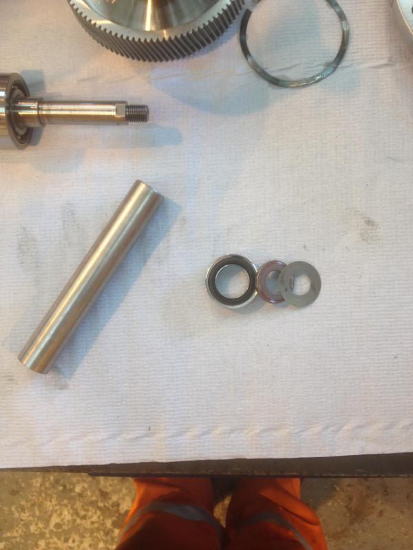
Picture of parts:
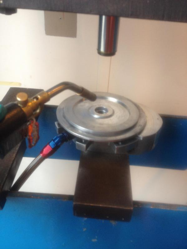
I then placed the casing into a vice (with the output shaft/bearings still attached), heated the impeller with a blow torch then removed the locking nut and impeller. once you remove these the output shaft assembly just pops out:
I melted the old output shaft seal but this was getting replaced anyway:
Then put the washers with the impeller for safe keeping:
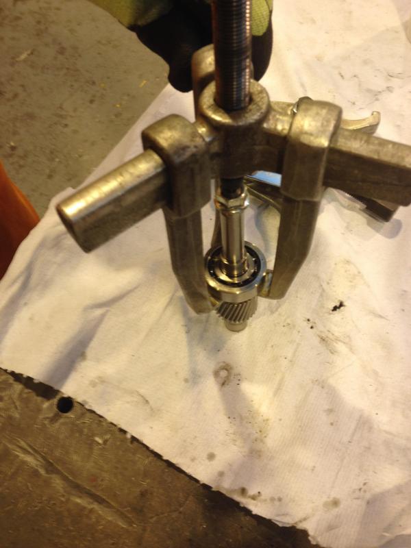
I then removed all bearings with bearing pullers
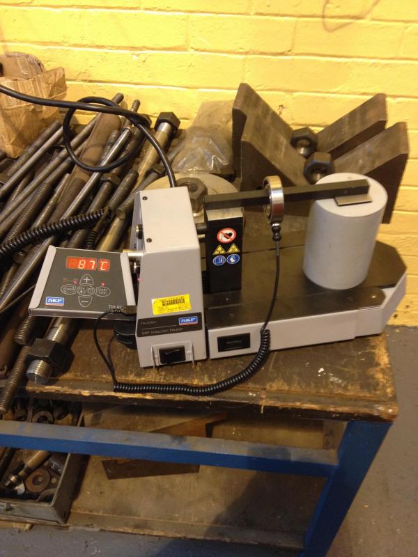
I removed all four bearings and refitted them using a bearing induction heater. If you haven't got a bearing induction heater just heat the bearings in some fresh motor oil to 100'C in an oven!:
WHEN ISTALLING THE NEW BEARINGS MAKE SURE YOU INSTALL THEM IN THE SAME ORINTATION AS REMOVED! NUMBERS FACING OUTWARDS!
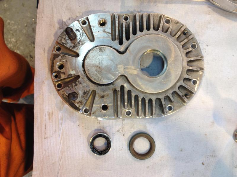
I then removed the input & output shaft seal with a press and hand tools:
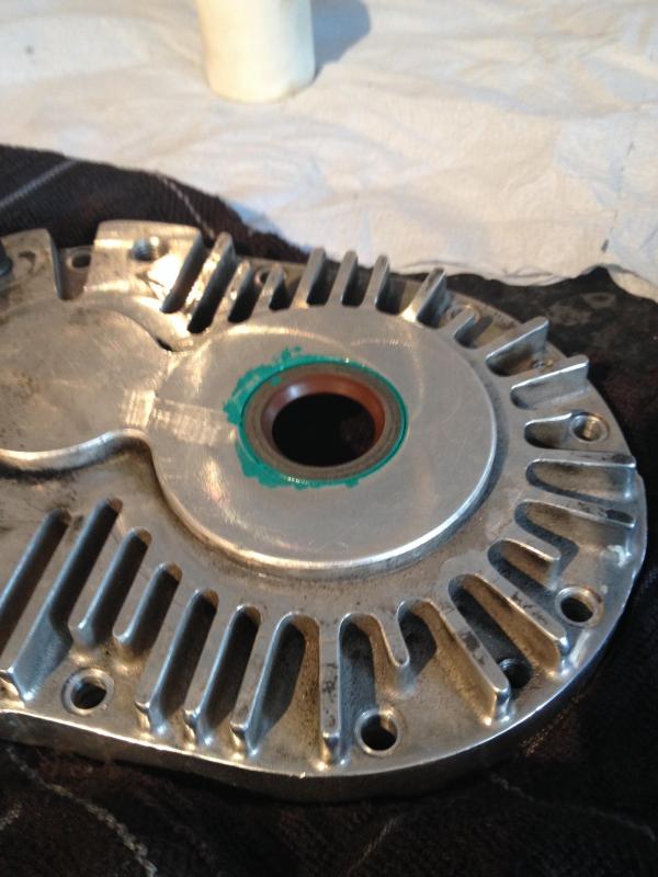
I then pressed in the new seals - Please note; you can easily damage the seals so please be cautious!!! You need to heat the casing with a blow torch (or this is how Paxton recommend). You must press the output shaft in on the inner race/sleeve ONLY! I used some 17mm round bar for the output shaft. The input shaft can be done by hand
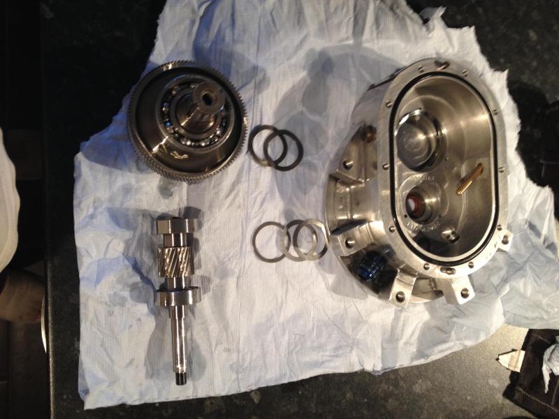
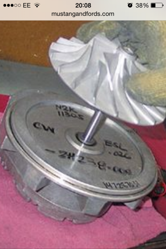
I then laid all the components out and re-assembled:
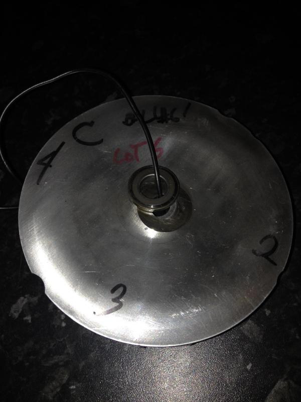
Once I'd reassembled all the parts within the casing. I installed the rear cover with the allen key bolts. Then placed the input shaft into a vice and clamped it. Heated the impeller with a blow torch and dropped the impeller back onto the output shaft.
Like this:
Then I screwed on the lock nut and tightend.
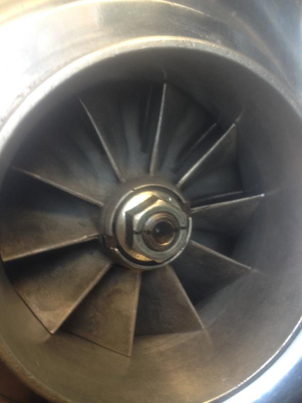
You can now re-install the impeller, volute and pulley.
I then fitted the charger to the car. I spun the input shaft by hand (with the belt removed), I could hear the impeller touching the volute so I clamped the input shaft with a pair of stilsons and tighten the impeller locking nut. I tightened it to what felt tight to me. Please go careful as you could break the helical gears if excessive force is applied!
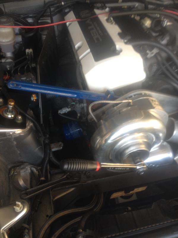
I then marked the lock nut with a line to see if it moves - which it hasn't so far.
Picture of parts:

I then placed the casing into a vice (with the output shaft/bearings still attached), heated the impeller with a blow torch then removed the locking nut and impeller. once you remove these the output shaft assembly just pops out:


I melted the old output shaft seal but this was getting replaced anyway:

Then put the washers with the impeller for safe keeping:

I then removed all bearings with bearing pullers

I removed all four bearings and refitted them using a bearing induction heater. If you haven't got a bearing induction heater just heat the bearings in some fresh motor oil to 100'C in an oven!:
WHEN ISTALLING THE NEW BEARINGS MAKE SURE YOU INSTALL THEM IN THE SAME ORINTATION AS REMOVED! NUMBERS FACING OUTWARDS!

I then removed the input & output shaft seal with a press and hand tools:

I then pressed in the new seals - Please note; you can easily damage the seals so please be cautious!!! You need to heat the casing with a blow torch (or this is how Paxton recommend). You must press the output shaft in on the inner race/sleeve ONLY! I used some 17mm round bar for the output shaft. The input shaft can be done by hand


I then laid all the components out and re-assembled:


Once I'd reassembled all the parts within the casing. I installed the rear cover with the allen key bolts. Then placed the input shaft into a vice and clamped it. Heated the impeller with a blow torch and dropped the impeller back onto the output shaft.
Like this:

Then I screwed on the lock nut and tightend.
You can now re-install the impeller, volute and pulley.
I then fitted the charger to the car. I spun the input shaft by hand (with the belt removed), I could hear the impeller touching the volute so I clamped the input shaft with a pair of stilsons and tighten the impeller locking nut. I tightened it to what felt tight to me. Please go careful as you could break the helical gears if excessive force is applied!

I then marked the lock nut with a line to see if it moves - which it hasn't so far.
 12-03-2014, 04:31 AM
#3
Thread Starter
For information:
I bought the bearings from a UK supplier no problem, they cost my £150
Parts I used:
X2 SKF 6206 C3 bearings
X2 Barden 203H bearings
X1 input shaft seal
X1 output shaft seal - 30mm
Seals can be bought from here:
http://www.superchargerrebuild.com/paxton/
I did purchase a seal from JBO but I didn't like the type of output shaft seal so opted for the OEM type from the above.
Any questions please ask, I typed that lot as quickly as possible

 12-03-2014, 05:06 AM
#7
Great information! I recently rebuilt my Paxton 1000 as well and my impeller only had one shim on it, compared to two on yours! Seems that there is quite a bit of variation with their builds. Also, from my research, the impeller nut needed 35 ft/lbs, or at least, that's what a paxton manual said. Thanks for the write up!
Trending Topics

 12-03-2014, 08:50 AM
#9

Nice write up. 
As long as you dont over spin the blowers rated speed, or over tighten the pulley belt, ive seen 150k+ miles on these units before a rebuild was needed. They all sound like a coffee grinder at idle.
As long as you dont over spin the blowers rated speed, or over tighten the pulley belt, ive seen 150k+ miles on these units before a rebuild was needed. They all sound like a coffee grinder at idle.