My never ending project - FullRace Prostreet (GT3076R)
 10-18-2012, 12:22 AM
#121


Join Date: Nov 2003
Location: Socal - SFV
Posts: 10,727
Likes: 0
Received 0 Likes
on
0 Posts
Originally Posted by Sarek' timestamp='1350416410' post='22086861
Thanks! I'll take a picture later today. But to be honest, now that I have the motor in the car I would have routed them slightly different. But I only had to do it once so far and its working great!
 Would be really nice if you bother to take a couple of seconds in paint or something just to show how you would recommend to run the lines differently!
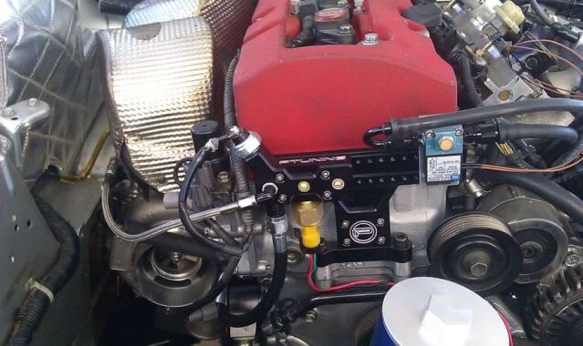
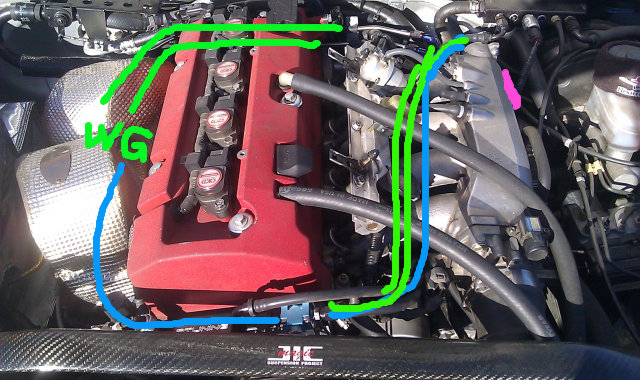
The green is how it's routed right now. Under the intake mani and via vacuum block near the brake booster.
The blue is how I think I should've done it. The pink is where I was going to originally mount the solenoid.
hope that helps and that your'e not in too much awe of my mspaint skills

 You also got me thinking I should go get a PTuning oil distribution block...
  10-18-2012, 12:13 PM
#123
Join Date: Nov 2003
Location: Socal - SFV
Posts: 10,727
Likes: 0
Received 0 Likes
on
0 Posts
 I think it's a great piece!
 10-23-2012, 02:17 AM
#126

Thread Starter
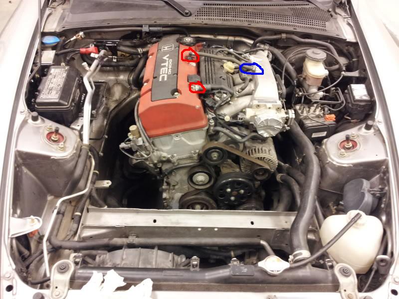
I'm also installing a Fullblown catch can and a PTuning oil and vacuum distribution block. With that case, can I use two areas marked in red to vent to the catch can, and the blue one two the vacuum distribution block? Or what would be a good way to do it?
10-23-2012, 10:58 AM
#127
Join Date: Nov 2003
Location: Socal - SFV
Posts: 10,727
Likes: 0
Received 0 Likes
on
0 Posts
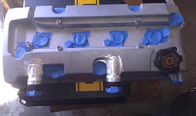
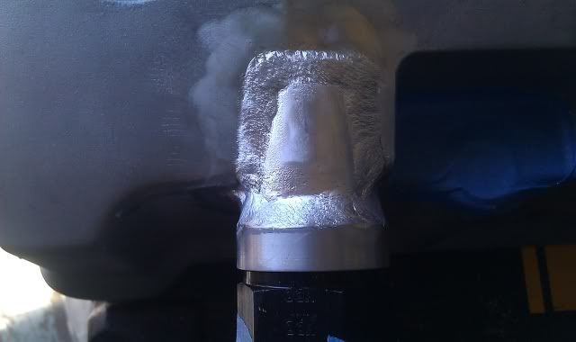
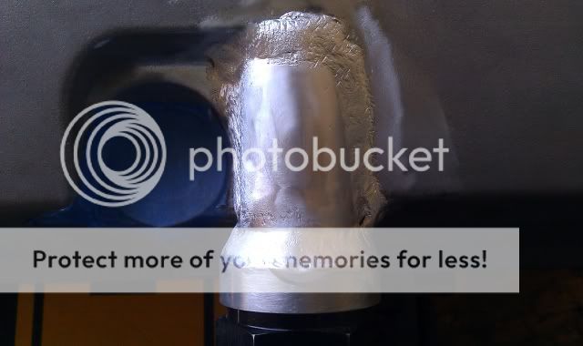
Red circless...You may need bigger holes than the OEM location. With only 14-15psi and venting to the atmosphere, I'm still blowing my dipstick out at full throttle. I'm going to use -12AN in the same locations. I'm sure it's overkill, but I wanted to fit the biggest one I can there.
Those locations are great because of the baffle underneath. It's just a little more effort to open up the hole and fab the fitting on and making sure your hood can still close.
I love pictures!
 10-23-2012, 11:12 AM
#128
Thread Starter
Thanks! And pictures are allways great About the red circles, I was just thinking about the locations. The plan is to use AN -10. Could the outlets be one straight out to the side, and the other 90 degrees ut like the standard coupler, or should both go out straight to the side? About the blue one, could I use the brake booster to "feed" the vacuum block?
About the red circles, I was just thinking about the locations. The plan is to use AN -10. Could the outlets be one straight out to the side, and the other 90 degrees ut like the standard coupler, or should both go out straight to the side? About the blue one, could I use the brake booster to "feed" the vacuum block?
10-23-2012, 11:24 AM
#129
Join Date: Nov 2003
Location: Socal - SFV
Posts: 10,727
Likes: 0
Received 0 Likes
on
0 Posts
Thanks! And pictures are allways great About the red circles, I was just thinking about the locations. The plan is to use AN -10. Could the outlets be one straight out to the side, and the other 90 degrees ut like the standard coupler, or should both go out straight to the side? About the blue one, could I use the brake booster to "feed" the vacuum block?
About the red circles, I was just thinking about the locations. The plan is to use AN -10. Could the outlets be one straight out to the side, and the other 90 degrees ut like the standard coupler, or should both go out straight to the side? About the blue one, could I use the brake booster to "feed" the vacuum block?Yes on the brake booster. That's how mine is routed. IIRC, there is also a one way valve in the brake booster hose. I'll try to get a picture of that too! lol. I'm using a golden eagle VB like this one:
 10-23-2012, 11:40 AM
#130
Thread Starter
Would there be an advantage of any kind to tap the brake booster line instead of taking the vacuum line from the intake manifold? Or would the function be the same?