Another S2K race car project


 06-26-2015, 05:42 PM
#32
Registered User
Thread Starter

Join Date: Nov 2011
Posts: 28
Likes: 0
Received 0 Likes
on
0 Posts
Wow... It's been 3 years and I wasn't posting anything about this project. Sorry!
I will have to start with 2.5 years back than:
Here’s a master model of front bodywork. About this way it looked before taking molds.
Than jelcoat

Than layers of fiberglass.


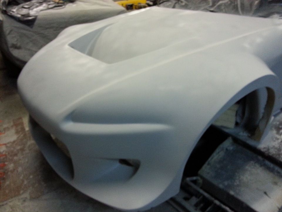
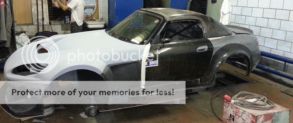
Than we took carbon fiber parts out the molds and mocked up on the chassis. We kind of liked it . Entire front bodywork weighted in at 15.4kg (~34lbs). It was fresh out of the mould so required trimming, finishing work etc.

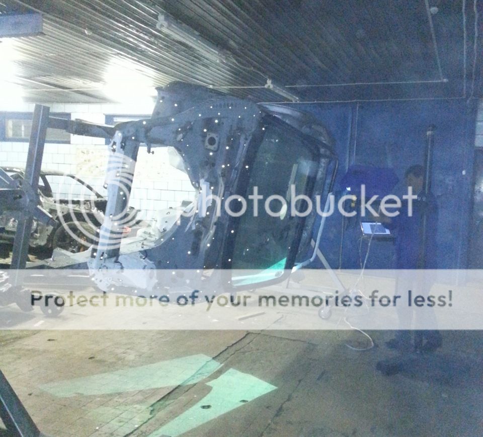
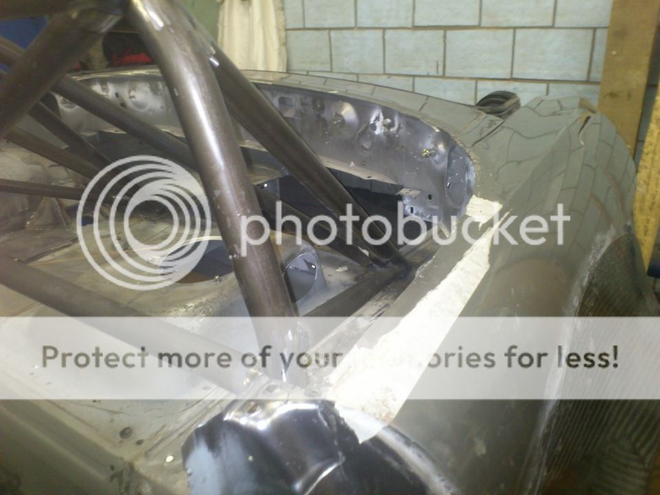
Than it was time to rescan the chassis (I didn’t have enough data from initial scan). We placed chassis on stands and scanned it.
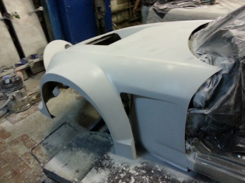
Than initial fitting and trimming bodywork on the car.

Lot's more to post and I will try doing it tomorrow.
So far you can look at my another project: http://www.gtrlife.com/forums/topic/...de-name-ngt-r/
Thanks
Ted
I will have to start with 2.5 years back than:
Here’s a master model of front bodywork. About this way it looked before taking molds.
Than jelcoat
Than layers of fiberglass.
Than we took carbon fiber parts out the molds and mocked up on the chassis. We kind of liked it
. Entire front bodywork weighted in at 15.4kg (~34lbs). It was fresh out of the mould so required trimming, finishing work etc.Than it was time to rescan the chassis (I didn’t have enough data from initial scan). We placed chassis on stands and scanned it.
Than initial fitting and trimming bodywork on the car.
Lot's more to post and I will try doing it tomorrow.
So far you can look at my another project: http://www.gtrlife.com/forums/topic/...de-name-ngt-r/
Thanks
Ted
 06-27-2015, 08:52 AM
#34
Registered User
Thread Starter
Join Date: Nov 2011
Posts: 28
Likes: 0
Received 0 Likes
on
0 Posts
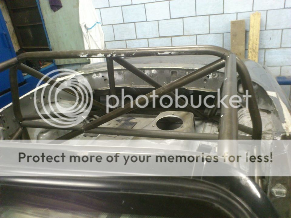
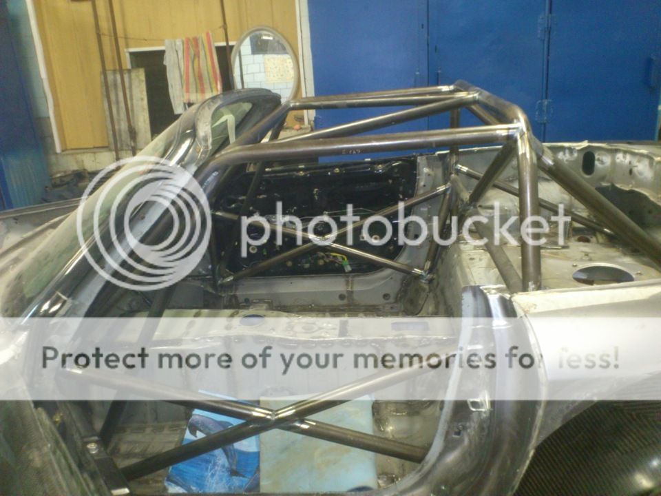
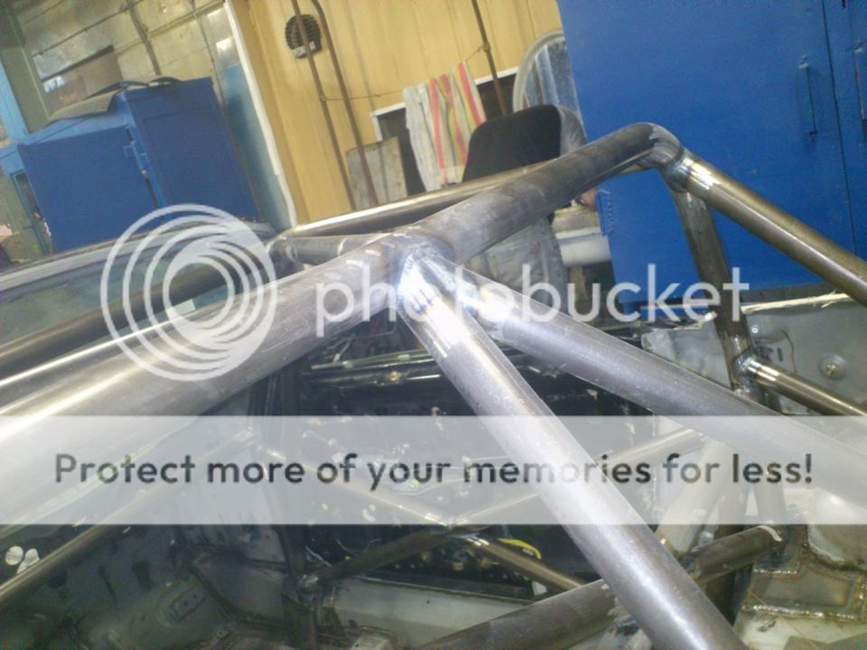
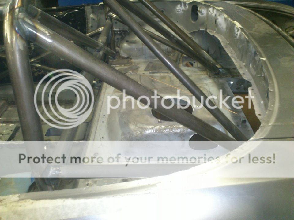
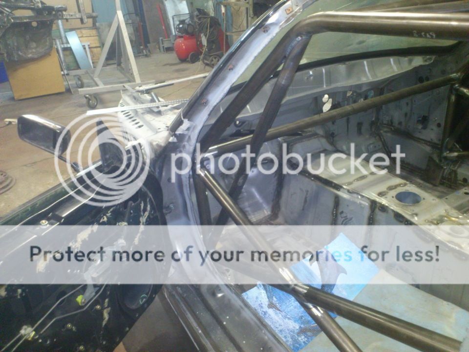
Time for chassis work. Fully seam welded.
Spot welding used for production vehicles doesn’t provide sufficient integrity of separate stampings used by factory to construct chassis. Properly seam welded chassis would gain from around 80% to 110% in torsional stiffness which is absolutely vital for handling. Most highly stressed areas (such as areas around suspension subframes, lower sides seals etc.) are welded with continuous welds and less important areas with “stitch” welding (~25mm weld, 25mm gap, 25mm weld and so on). There’s one very important thing – excessive heat would deteriorate steel properties. Proper technique is to weld a stitch of 10-12mm (short enough so metal is not overheated) than leave a ~ 100mm gap than apply next short weld. After placing say 10-15 "stitches" with large gaps between them on left side welder would move to right side of the car and repeat the process there while left side is cooling. Than get back on left side and place a weld in the middle of each gap and move to the right side and repeat it there and so on until one continuous weld is achieved where needed. Doing it this way is a lot more labor intensive and time consuming but it pays dividends in terms of end result – strong and stiff chassis which could be used as a base to build a proper race car. (Most of you already know it all better than I do)
Here’s a couple of shots. First tack weld, than checking every “node” for perfect fit, fine finish the notching, clean sand weld areas, etch, final weld:
Nothing special but it worth to compare it to this video where one can see their build log as well as roll cage/welds. It was considered as world fastest S2000 back in 2012 (It was relevant at the time of I doing this part of project)
[media]https://youtu.be/JrAYC6zH5mY[/media]
06-27-2015, 09:15 AM
#35
Registered User
Thread Starter
Join Date: Nov 2011
Posts: 28
Likes: 0
Received 0 Likes
on
0 Posts
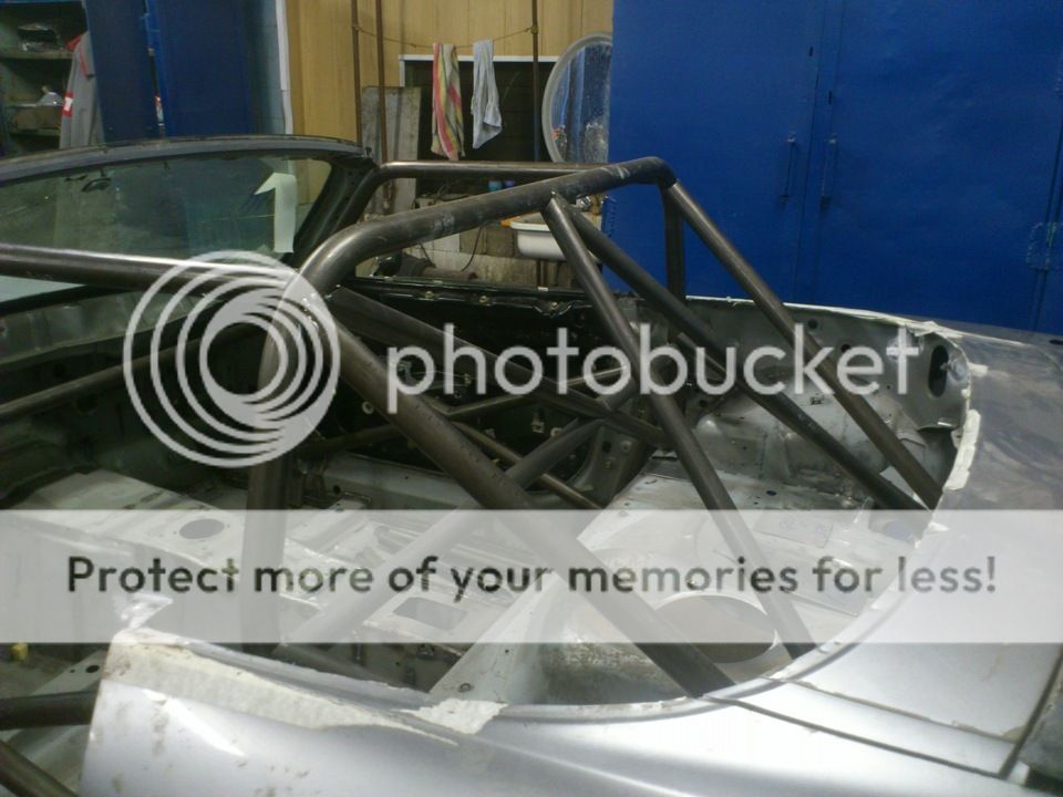
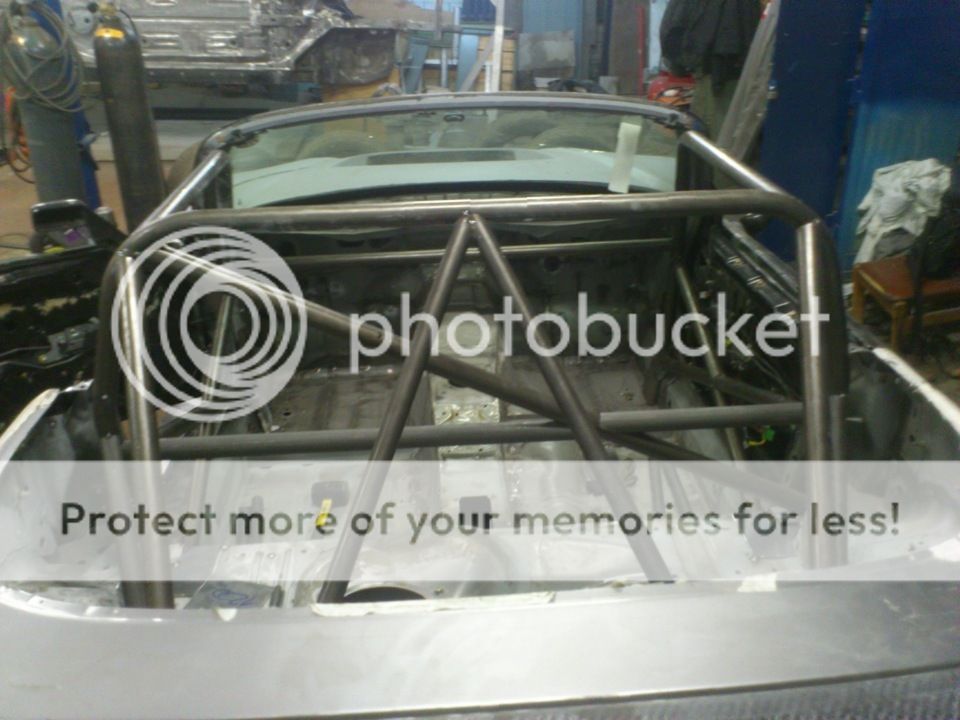
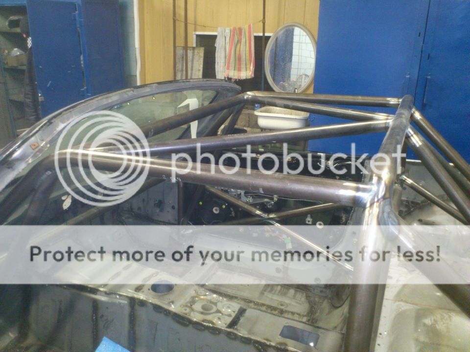
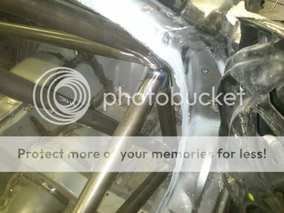
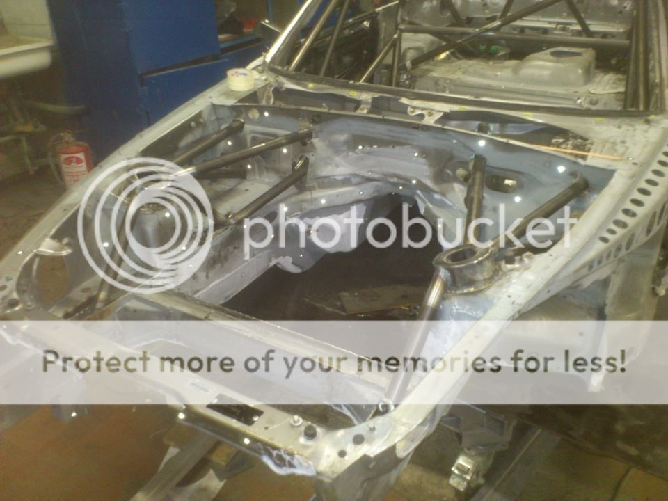
Front chassis part (what’s under the carbon fiber skin).
Initial fit of the tubes.
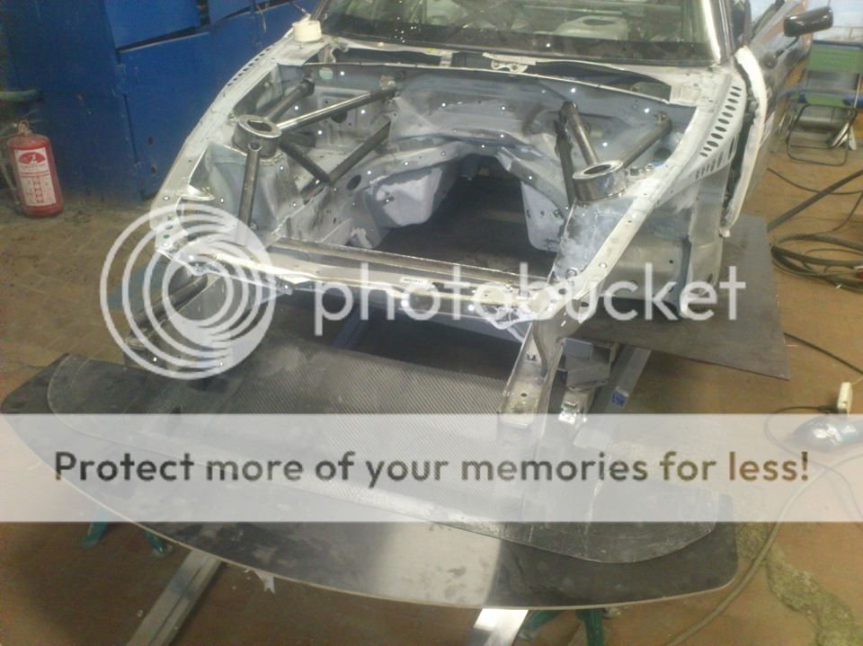
This will make for fairly stiff (torsional) front part of chassis – triangles resist deformation in vertical, longitudinal and lateral directions.
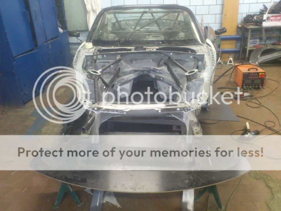
Here’s front part final welded. Now we have more or less suitable handling platform to build our geometry on:
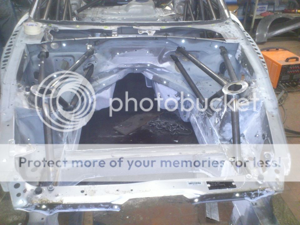
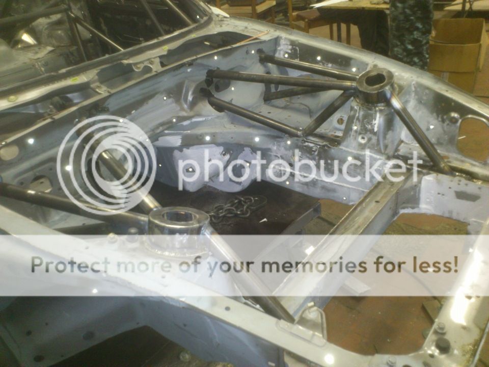
Chassis is 90% ready and now it’s time for subframes and suspension members.
Initial fit of the tubes.
This will make for fairly stiff (torsional) front part of chassis – triangles resist deformation in vertical, longitudinal and lateral directions.
Here’s front part final welded. Now we have more or less suitable handling platform to build our geometry on:
Chassis is 90% ready and now it’s time for subframes and suspension members.

 06-28-2015, 08:58 AM
#37
Registered User
Thread Starter
Join Date: Nov 2011
Posts: 28
Likes: 0
Received 0 Likes
on
0 Posts
We do uprights in many different ways – CNC 7075 alu, cast than machined Ti alloys, fabricated uprights (steel or ti) according to budget, tech. regulations and targets.
06-28-2015, 10:50 AM
#39
Originally Posted by DavidNJ' timestamp='1435456439' post='23662991
Did you modify the suspension geometry to work at a lower ride height? Did your rules allow custom uprights and did you consider making CNC uprights for a revised geometry?
We do uprights in many different ways – CNC 7075 alu, cast than machined Ti alloys, fabricated uprights (steel or ti) according to budget, tech. regulations and targets.
That is beautiful. I helped design the uprights on our FSAE car when I was in school.