Rear Wing Design
 08-11-2016, 07:05 PM
#1

Thread Starter

I've started a new project at home to create my own rear wing, mainly for fun and because I'm addicted to making things. The thing that inspired me is the McLaren P1 wing that is able to be completely adjustable. That is my goal for my project, even though I will never go fast enough to be able to make use of being able to lower my wing.
I started by selecting an airfoil to begin testing with. This will not be the final cross section, but just something for me to start CFD analysis with. I chose the NACA-633-618 as shown below.

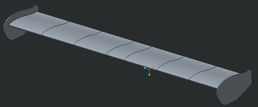
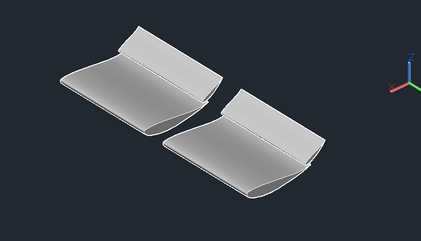
What I plan on doing is creating the main body using 7 separate sections, that will then be joined together. The different pieces are keyed joints that will be epoxied together, then overlaid with composite. The first prototype will be made primarily of additive materials, with a foamed interior. I haven't decided on the materials for the final product yet, but it will be primarily reinforced composite. Endplates, mounts and stands will all be 6061 aluminum.
Here is a rough shot of what I have in mind:
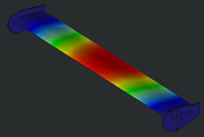
My design goal is to be able to hold 1000 lbs of uniform load, with a maximum deflection of .05". Currently I am at .30" (using polycarbonate as a material) so I have some tweaking to do to get there, but I'm not worried.
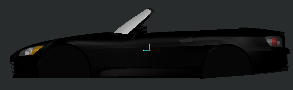
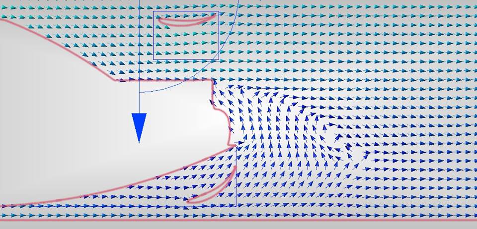
Once I have achieved that, I am going to run CFD on my S2000 model to determine the optimal height, AOA and airfoil design. I am a mechanical/aerospace engineer so I work with this stuff almost on a daily basis, but this time I am trying to avoid lift!
I'm lucky enough to have a 3D-printer, mill and design tools at home so I should be able to move along fairly unimpeded depending on how busy I am at work. If you have any comments or suggestions, feel free to post them up. I am not thin-skinned and can take constructive criticism.
The one thing I do need help on is if someone could take some measurements for me for the common S2000 mounting locations. That is the only thing preventing me from designing my stands/mounts as I do not have a wing currently and my trunk is not drilled with the factory holes. Or maybe someone like APR provides a drill template for their off the shelf products.
Thanks everyone!
I started by selecting an airfoil to begin testing with. This will not be the final cross section, but just something for me to start CFD analysis with. I chose the NACA-633-618 as shown below.
What I plan on doing is creating the main body using 7 separate sections, that will then be joined together. The different pieces are keyed joints that will be epoxied together, then overlaid with composite. The first prototype will be made primarily of additive materials, with a foamed interior. I haven't decided on the materials for the final product yet, but it will be primarily reinforced composite. Endplates, mounts and stands will all be 6061 aluminum.
Here is a rough shot of what I have in mind:

My design goal is to be able to hold 1000 lbs of uniform load, with a maximum deflection of .05". Currently I am at .30" (using polycarbonate as a material) so I have some tweaking to do to get there, but I'm not worried.

Once I have achieved that, I am going to run CFD on my S2000 model to determine the optimal height, AOA and airfoil design. I am a mechanical/aerospace engineer so I work with this stuff almost on a daily basis, but this time I am trying to avoid lift!

I'm lucky enough to have a 3D-printer, mill and design tools at home so I should be able to move along fairly unimpeded depending on how busy I am at work. If you have any comments or suggestions, feel free to post them up. I am not thin-skinned and can take constructive criticism.
The one thing I do need help on is if someone could take some measurements for me for the common S2000 mounting locations. That is the only thing preventing me from designing my stands/mounts as I do not have a wing currently and my trunk is not drilled with the factory holes. Or maybe someone like APR provides a drill template for their off the shelf products.
Thanks everyone!
 08-11-2016, 10:39 PM
#2

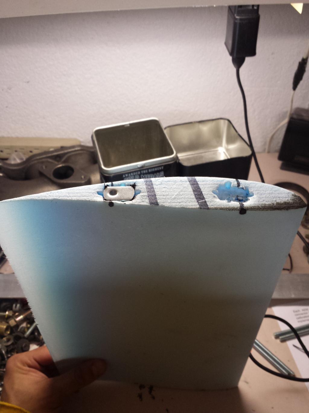
I know one other gentleman that made his own wing. He was kind enough to share the details with me at WSIR. He got a wing cross section for a automotive application that seemed to have the desirable characteristics and then sent the cross section to these guys:
https://flyingfoam.com/
Then he laminated the result.
The end result was light, cheap, modular and overall pretty impressive:
Lots of great pictures etc of his result here
https://flyingfoam.com/
Then he laminated the result.
The end result was light, cheap, modular and overall pretty impressive:
Lots of great pictures etc of his result here

 08-14-2016, 02:38 PM
#4

I wouldn't worry too much about deflection so long as you can make the front spar considerably stiffer than the rear - should be easy enough, mine are (deflection tests in my project thread, much higher mesh than that one) - that way your wing will just loose AoA as the load increases, not a bad thing so long as you can control/damp it (internal foam does it fairly well).
You need to model your mountings too, they'll make a massive difference to how and where the wing deforms.
The main reason I ran such high quality meshes on mine were because I have slot gaps to worry about with a 3 element wing, but the endplates/mounts shifted the pivots so much that most of the deflection occurs equally across all 3 maintaining the gaps anyway.
08-15-2016, 05:16 PM
#5
Thread Starter
Yea, I am definitely going to do the mounts next and rerun the load case. The image above was just a meshcheck, it's pretty much a fixed/fixed beam at this point.
Can you direct me to your thread?
Can you direct me to your thread?
08-17-2016, 05:03 AM
#6
The wing stuff is here:
https://www.s2ki.com/s2000/topic/971.../page__st__350
Rather old fashion way of doing things but I'm running on a shoe-string budget to get them build and mine need to be resistant to rocks and trees
https://www.s2ki.com/s2000/topic/971.../page__st__350
Rather old fashion way of doing things but I'm running on a shoe-string budget to get them build and mine need to be resistant to rocks and trees
08-19-2016, 11:38 AM
#7
Registered User
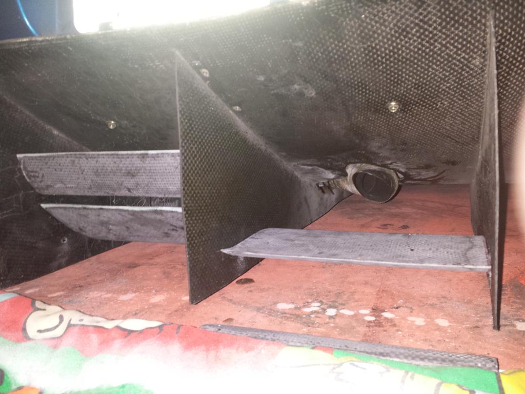
I used fiberglass foam core from matney models to do my rear diffuser.
I was going to 3d print them but the carbon is easy to make and the foam is really light weight.
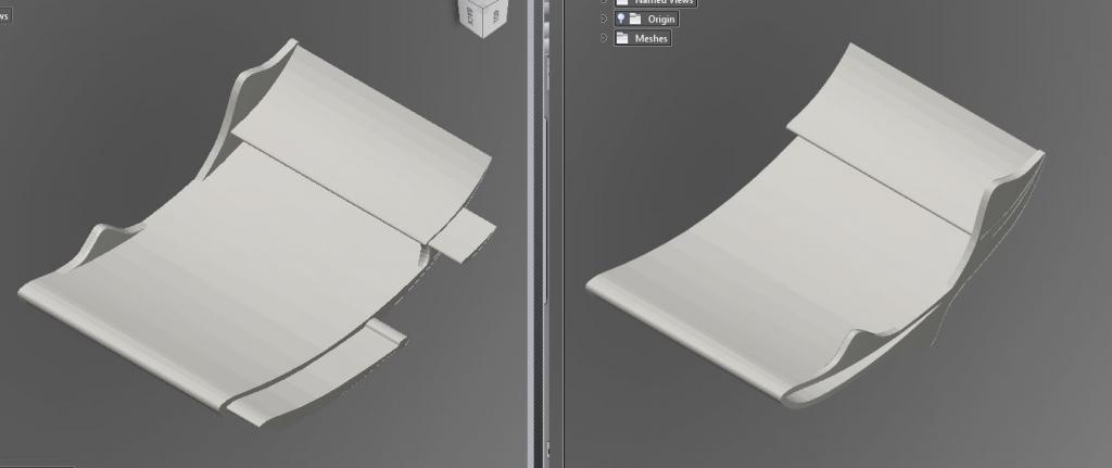
this is my design and what I ended up with.
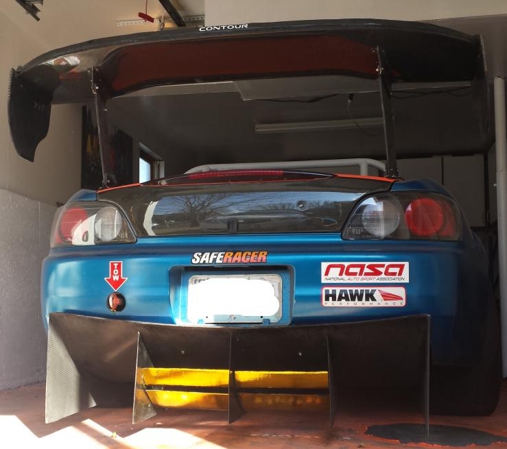
love seeing custom work. good luck!
I was going to 3d print them but the carbon is easy to make and the foam is really light weight.

this is my design and what I ended up with.


love seeing custom work. good luck!
Trending Topics
08-19-2016, 08:42 PM
#8
So, I'm not an engineer, but I do know polycarbonate from a different perspective. The use of it in optical lenses and a little with barriers.
Gererally, why polycarbonate is one of the most impact resistant materials, in optics and barriers it is consider pretty soft and bendable. So, given that, wouldn't you expect your deflection of a polycarbonate wing to be much greater than one of carbon laminate?
Gererally, why polycarbonate is one of the most impact resistant materials, in optics and barriers it is consider pretty soft and bendable. So, given that, wouldn't you expect your deflection of a polycarbonate wing to be much greater than one of carbon laminate?
08-21-2016, 05:51 AM
#9
Thread Starter
So, I'm not an engineer, but I do know polycarbonate from a different perspective. The use of it in optical lenses and a little with barriers.
Gererally, why polycarbonate is one of the most impact resistant materials, in optics and barriers it is consider pretty soft and bendable. So, given that, wouldn't you expect your deflection of a polycarbonate wing to be much greater than one of carbon laminate?
Gererally, why polycarbonate is one of the most impact resistant materials, in optics and barriers it is consider pretty soft and bendable. So, given that, wouldn't you expect your deflection of a polycarbonate wing to be much greater than one of carbon laminate?
For testing purposes I can't produce many items out of carbon. My plan is to create a prototype out of polycarbonate (best material I can print out of) and then once the concept is proven, I am going to let a composite company use my prototype for a mold. The most expensive part of composites is creating the mold, so if I can get rid of that process the cost will be really cheap, relatively speaking.
I'm going to have some more updates on this soon. I changed my cross-sections recently to address some new research and I am debating removing the key/slot idea and going a different route.
07-10-2017, 10:02 AM
#10
Thread Starter
Haven't updated this thread in a while, but the wing is in production now. I am working with a composite company that is going to make the shape for me out of fiberglass and embed my end plate mounts to it. So I will be able to easily mount whichever design endplates I want. The mounting will also work for standard APR GTC-200 stand locations.
Would anyone be interested in having one made for them as well? I think it will cost around $350-$400 for the center section, end plates mounts embedded, and the mounting standoffs to work with the APR stands.
Would anyone be interested in having one made for them as well? I think it will cost around $350-$400 for the center section, end plates mounts embedded, and the mounting standoffs to work with the APR stands.