Help with aftermarket steering wheel horn wiring
 01-09-2011, 12:08 PM
#1

Thread Starter
Join Date: May 2010
Posts: 1,069
Likes: 0
Received 0 Likes
on
0 Posts
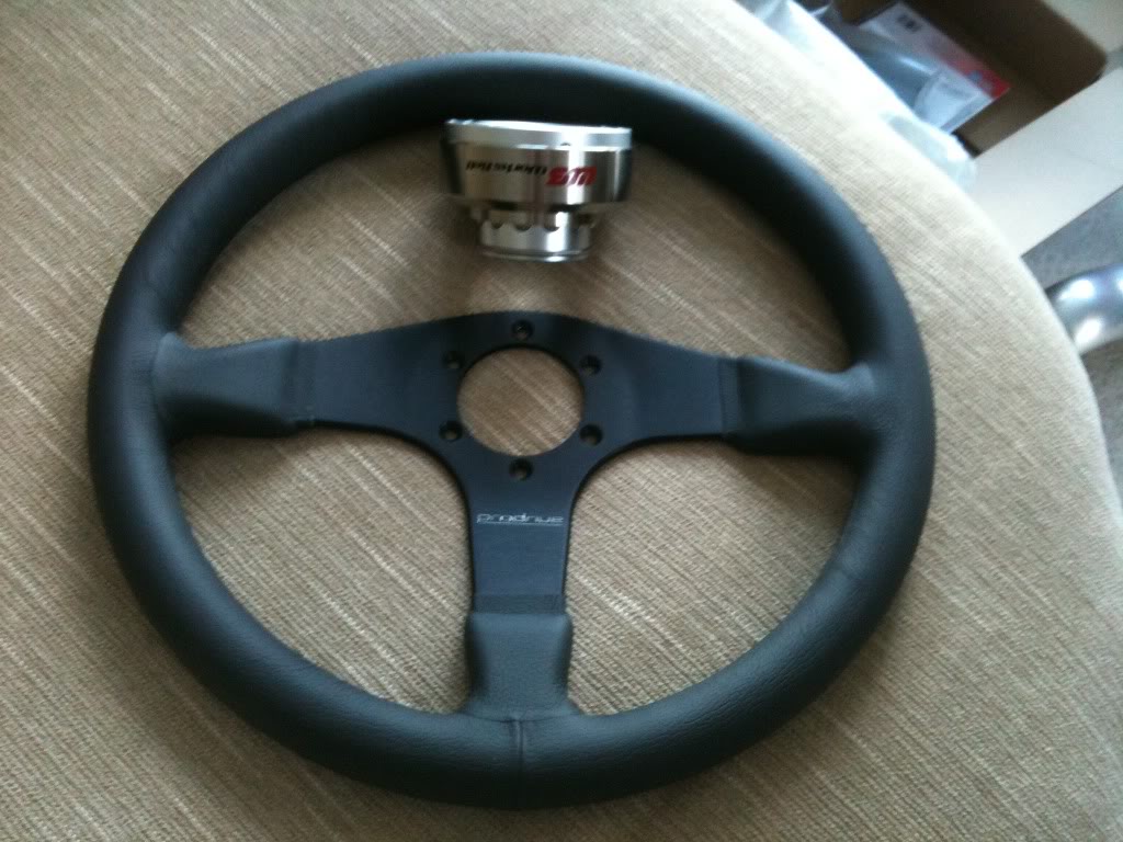
I picked up an 03 s2k a few weeks back and it came with an aftermarket steering wheel. Only problem is the horn dosen't work. So, i took it apart today to see if i could figure it out. I realized the horn in this car was only one wire so i figured it would just need to be grounded for it to work. So i ground the wire and sure enough, it works. So, I cut the factory connector off of the horn wire and soldered it to one of the contacts for the aftermarket steering wheel.
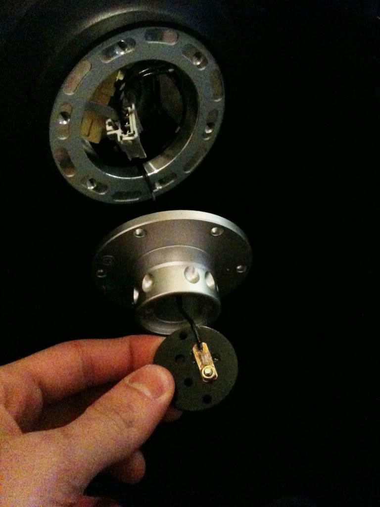
so then i srewed everything back together, mounted the wheel on and it diden't work. So i took the wheel apart and took the horn switch out. I'm a little confused about what is going on here..
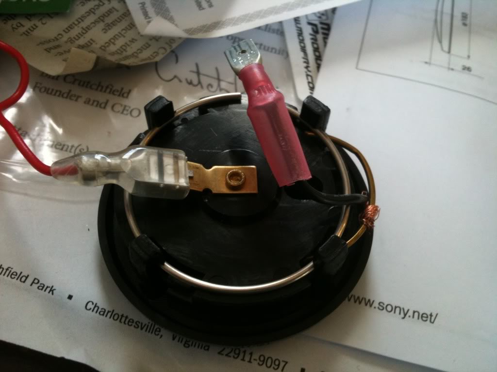
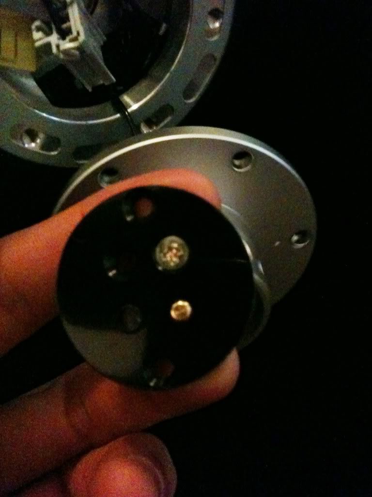
what is this for? Is this supposed to be the ground?
Basically, I need to find out how to ground this horn switch. Any help would be appreciated! Also, what kind of resistor would be good for the air bag connector to turn the light off? Like how many ohms? Just a regular one from radio shack will work fine? Thanks!
so then i srewed everything back together, mounted the wheel on and it diden't work. So i took the wheel apart and took the horn switch out. I'm a little confused about what is going on here..
what is this for? Is this supposed to be the ground?
Basically, I need to find out how to ground this horn switch. Any help would be appreciated! Also, what kind of resistor would be good for the air bag connector to turn the light off? Like how many ohms? Just a regular one from radio shack will work fine? Thanks!
 01-09-2011, 05:01 PM
#2


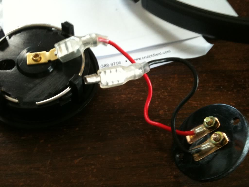
You almost have it; however you need to complete the circuit. Here's the complete path to ground: OEM horn connector, to hub black connector, to quick release black connector, to horn spade connector, to horn button ring to chassis ground.
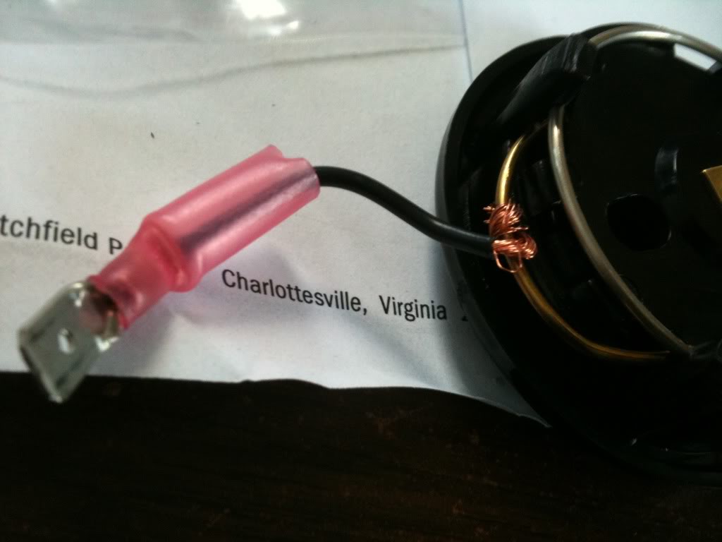
If that metal ring/clip is not making good contact with ground/chassis, the horn will not work. The other alternative, which you kinda started, is to place a wire on the horn button ring (soldered this, do not wrap). That connector would then feed all the way back thru the quick release and back to ground.
Also, you need a 2.2 ohm resistor for the airbag 'simulator'.
01-09-2011, 05:54 PM
#3
Thread Starter
Join Date: May 2010
Posts: 1,069
Likes: 0
Received 0 Likes
on
0 Posts
so you think its not working because the metal ring on the horn switch with the black wire wrapped around it isn't getting a good contact inside the metal hub? I think it is but can't think of any other reason why it wouldn't work. So i guess i could try to bend the metal wire in the horn switch out more so it will have a stronger contact with the inside of the metal hub. Or, I could solder that wire on to the thick horn switch wire and run it to the contact, then it should definitely work, right? and like i said earlier, only one of the 2 contacts is needed, correct?
01-09-2011, 06:19 PM
#4
Only one of two contacts are needed if the metal ring completes the circuit (ground). Otherwise, you'll need to use the other contact to ground internal to the hub.
If you have a meter, you could easily check continuity to verify ground. If you're sure the ring is making positive contact, the only other reason I can think of is that the material used for the quick release is non-conductive.
If you have a meter, you could easily check continuity to verify ground. If you're sure the ring is making positive contact, the only other reason I can think of is that the material used for the quick release is non-conductive.
01-09-2011, 06:35 PM
#5
Thread Starter
Join Date: May 2010
Posts: 1,069
Likes: 0
Received 0 Likes
on
0 Posts
ohhh maybe that is the case. It is a works bell and i'm not sure if it is conductive. If it isen't conductive and i have to use both contacts, i'm still a little confused on how to hook up both contacts : /
01-09-2011, 07:04 PM
#6
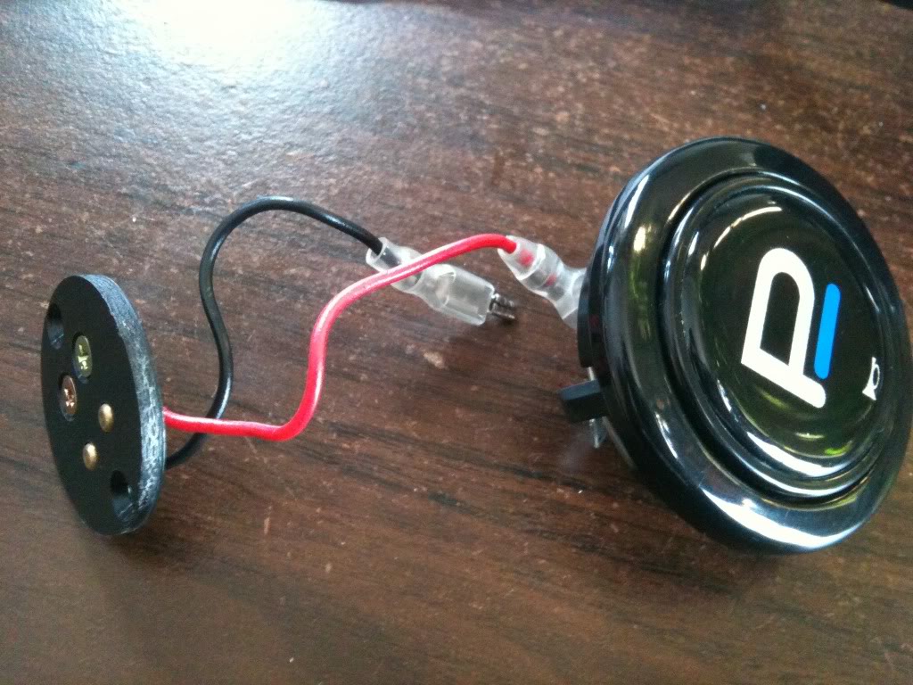
It's very simple. Maybe a picture will help illustrate:

Just follow the signal path from the OEM horn connector and back. The horn button just completes the circuit (e.g. switch). Make sense?
Just follow the signal path from the OEM horn connector and back. The horn button just completes the circuit (e.g. switch). Make sense?

