Clutch Change DIY
 01-22-2015, 09:20 AM
#1


Thread Starter
I was asked to create a DIY guide to changing your clutch by a couple of members recently. The following is a list of steps that I completed during my clutch change that does not follow the Honda recommended process, but is slightly simpler. However, it requires common sense and eyes! You undertake it at your own risk.
I already had the manifolds off the engine for another job (head gasket), so some of the initial work has no pictures I’m afraid. There are some in resource number 3. I may have forgotten one or two steps as a result, and some of the steps might not work whilst the intake manifold is still attached, but I think you’ll be ok.
Tools:
Resources:
1. https://www.s2ki.com/...st__p__21861880
2. https://www.s2ki.com/...ost__p__1036057
3. https://www.s2ki.com/...ost__p__7560891
4. https://www.s2ki.com/...eight-required/
5. Workshop manual pages 13-5 to 13-11 fordisassembly, 13-66 to 13-72 for assembly and torque settings.
From above the car:

Inside the Car:


Under the car:


Chris
I already had the manifolds off the engine for another job (head gasket), so some of the initial work has no pictures I’m afraid. There are some in resource number 3. I may have forgotten one or two steps as a result, and some of the steps might not work whilst the intake manifold is still attached, but I think you’ll be ok.
Tools:
- Various sockets and spanners (mainly 10, 12, 14, 17mm)
- Good fitting (ie not cheap) 6mm Allen key, or ideally ashort 3/8” drive 6mm hex bit
- ½” drive Universal Joint
- Pliers (long nose, ideally crooked)
- 2 trolley jacks and 2 or 4 axle stands
- Impact Driver if removing flywheel (including changing pilotbearing) or tall axle stands and a breaker bar
- Approx 2-3 feet of ½” drive extensions
- Torque wrench for reassembly
Resources:
1. https://www.s2ki.com/...st__p__21861880
2. https://www.s2ki.com/...ost__p__1036057
3. https://www.s2ki.com/...ost__p__7560891
4. https://www.s2ki.com/...eight-required/
5. Workshop manual pages 13-5 to 13-11 fordisassembly, 13-66 to 13-72 for assembly and torque settings.
From above the car:
- Disconnect battery.
- Remove air box. 10mm headed bolts.
- Remove Engine belt. 14mm bolt on the tensioner (don’t undo, just twist the tensioner to allow the belt to slip off)
- Remove black heat shield next to brake master cylinder (three 10mm bolts at its bottom – don’t completely remove the rear one, the hole in the shield is slotted)
- Remove exhaust manifold heat shield. 12mm bolts.
- Uncouple Exhaust Manifold from engine. 12mm bolts.You might be able to leave it attached, and just remove the catalytic convertor instead (fewer bolts, less awkward – but I haven’t tested this method).
- Remove top bolt of engine bumper (just in front of the engine, on the subframe). 10mm or 12mm bolt.
- Remove Alternator top bolt and loosen lower bolt (I completely removed it for ease of access, as there’s just a plug on the back other than these two bolts, I think). 14mm bolts.
- Disconnect sensor plugs at the back of the engine near the bulkhead – basically you need to be able to drop the engine by a few inches, so any cables need to be uncoupled.
- You might need to uncouple a hose or two as well (I had the entire intake manifold removed).
- Remove upper starter bolt using approx 2 feet of extensions, entering where the alternator usually sits (but you’ve moved/removed it). 14mm bolt.
- Beware of knocking/levering against the knock sensor, which is on the side of the engine approx. half way along it, beneath the intake manifold. I had already removed the manifold, so you can see the location of the bolt here:
Inside the Car:
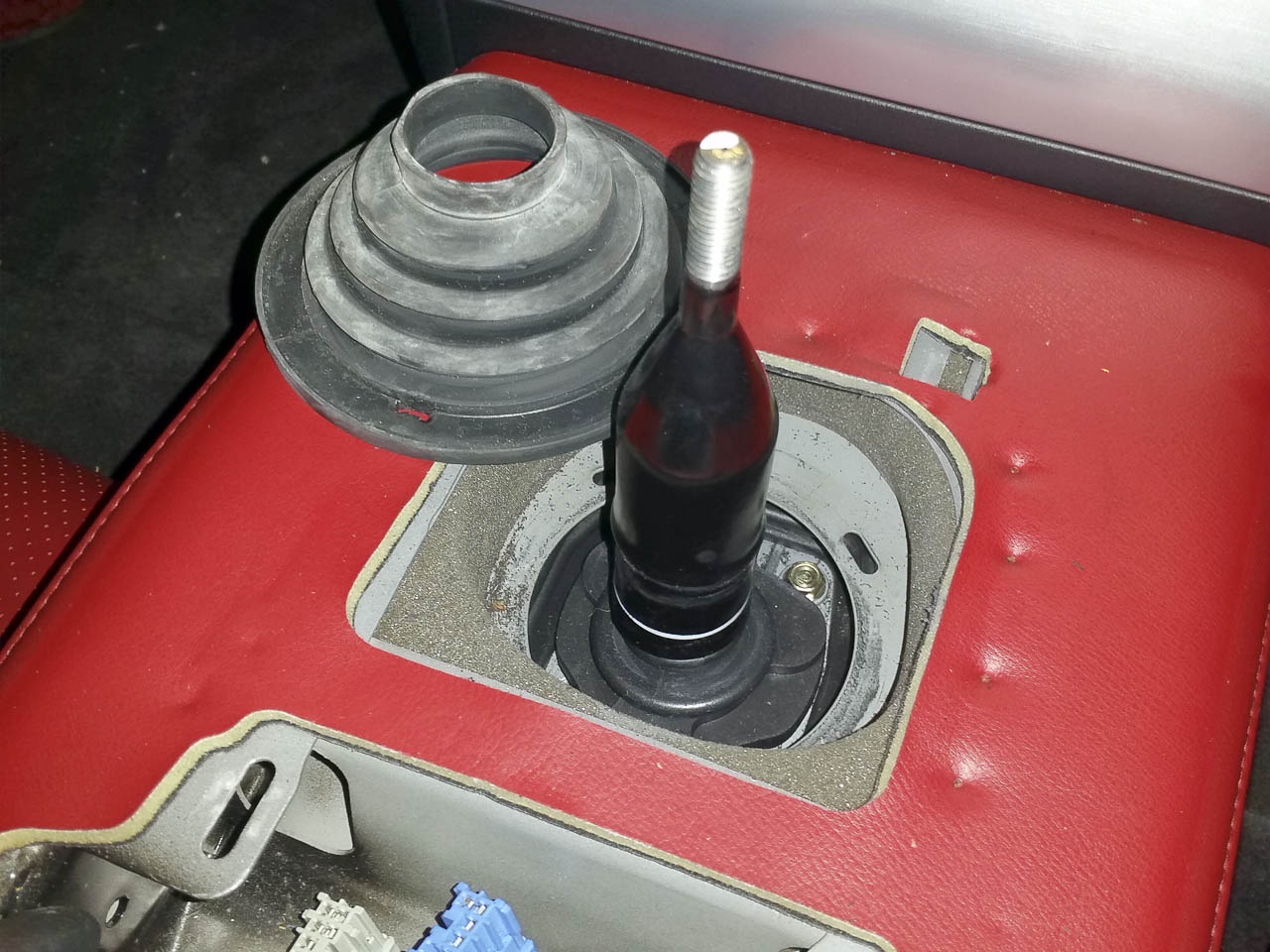
- Remove the gear knob (locking nut underneath, then unscrew the knob).Can’t remember the size, as my new knob doesn’t have a nut. It’ll be 12-14mm.
- Pull the handbrake on hard. This makes the console trim easier to remove and holds the propshaft still for later.
- Pull the centre console trim directly upwards and unplug the plugs from the backs of the switches (each one has a little tab to depress then they slide out easily). Remove the trim completely.
4. Gently put a flat bladed screwdriver into the gaps in the gearstick’s rubber surround, between the rubber and the white plastic ring. Push against the white plastic to release each of the 4 tabs. The area of the ring near each tab should gently ‘spring up’ as it’s released. Remove the white ring.
5. Slide the rubber boot up and off the gear lever.
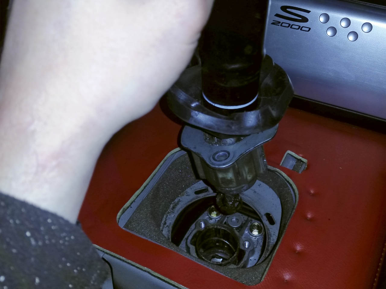
6. Lift the second rubber boot and undo the three 10mm bolts underneath it. Lift the gear lever and remove it.
Under the car:
1. Jack up the car and place on axle stands. I did this job on 4 axlestands with about 350mm clearance from the floor to the sills. I’m not a bigguy and it was ok. Jacking up higher will give you more room to work under thecar. Just make sure it is close enough to the ground that your trolley jack canlift the engine approx 3-4 inches upwards to clear the threads of the enginemounts. I’ve also been informed that you can do the job just on 2 axle stands,but clearly the bottom of the gearbox and engine (where you will place thetrolley jack) will not be parallel to the floor and the front of the car willbe further up in the air. I have no experience of this method.
2. Remove the lower two bolts of the rubber bumper in front of the engine(for which you previously removed the top bolt). 12mm bolts. Remove the rubber bumper. If you struggle to get it off the subframe, you can pull the rubber tabs from the metal and remove the rubber to give more room, then unclip the metal from the subframe.
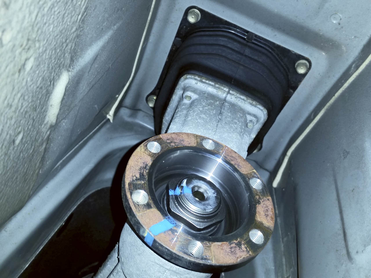
3. Remove the propshaft. 6 x 6mm hex cap head bolts at either end. You’ll need to turn the propshaft after the first 3 on each end in order to get to all the bolts (release the handbrake!). There isn’t much room for a 3/8” drive‘socket’ due to the shape of the shaft, so you’ll need a short one for the front bolts, or a close fitting allen key and some strength!
4. Remove the two bolts holding the clutch slave cylinder to the gearboxand let the cylinder unit gently down. Zip tie it somewhere out the way if it’s hanging by the hose (although I left it hanging and was careful not to tug on it). Do not undo the hydraulic hose bolt! Pull the clutch fork out of its pivot groove.
5. On the passenger side of the engine, there is a short ground cable thatis screwed to the subframe. I had just enough slack to do the rest of the job without removing one end, but you might not be so lucky. I would remove this from the subframe.
6. There are a number of cables along, up and over the gearbox (reverse sensor, VSS sensor, O2 sensors etc), all generally part of the same harness.Unplug these and detach the clips from the brackets. In some cases, it’s easiest to unbolt the bracket. There is one cable that stays attached to the gearbox and doesn’t need removing (plug on one end, sensor on the other, if I remember correctly). There’s also a bracket nearly on the engine block, on the passenger side of the gearbox. Just trace them all through and make sure you get them all. You will probably have to wait until you drop the gearbox for a couple of the ones on the top.
7. Remove the four bolts around the shifter housing to detach the rear ofthe gearbox from the chassis. 4x 10mm bolts, if I remember correctly.
8. Now you have cleared the gearbox of restrictions, you can place a trolley jack under it, somewhere in front of the mounting bracket. Jack it up and take the load of the gearbox.
9. Remove the bolts holding the gearbox mount to the chassis. 3x14mm bolts I think.
10. I also removed the two bolts holding the mount to the gearbox, so I could place some wood between the rubber mounts to place the 2[sup]nd [/sup]jack on. You could get away with jacking straight on to the mount, but it’s a bit wobbly on the rubbers. Once you’ve got the 2[sup]nd[/sup] trolley jack supporting the weight, remove the 1[sup]st[/sup] jack.
11. Lower the gearbox by a couple of inches. Just enough to let you remove the rest of the cables/plugs/clips.
12. Now it’s time to jack up the engine. Remove the nuts from the top and bottom of each engine mount (3 x 14mm I think, one on top, two underneath, on the bottom of the subframe). Place some padding (old rage, sponge, anything)between the engine and crossways stiffening brace below the sump. It will betaking the weight of the engine.
13. Place a jack under the section of the sump which has been ‘filled in’between the cooling vanes/ridges. Jack it up just high enough to remove the engine mounts (wiggle and manoeuvre them if necessary). It’s helpful to have someone above checking that nothing is bumping into each other in the engine bay and that nothing is being too stretched or snagged. You may have to manoeuvre the exhaust manifold to let the engine rise in a straight line. You may have to move the jacking point left or right, forward or backward to get it to rise in a straight line too.
14. Once the engine mounts are removed, lower the engine gently on to the subframe cross brace, again checking for snagging etc. You will also need to lower the gearbox at a similar rate, to avoid the air con pump touching the subframe. You don’t want that taking the weight of the engine! Be careful to move the exhaust out the way as you do it, especially watching the O2 sensors.
15. Once the engine is resting on the subframe, if you need to, lower the gearbox far enough to make some room around the top bell housing bolts. The one on the driver’s side is the most constrained. Make sure the back of the engine doesn’t hit the bulkhead.
16. Place the jack you used for the engine under the front portion of the gearbox (so you have one front and one rear under the gearbox). Make sure the wheels are facing along the length of the car so the jacks can roll the gearbox away from the engine. I didn’t, and ended up sliding one of the jacks, which was ok as it has a wide roller at the front, and was on carpet. Bit awkward though.
17. Now wedge some wood between the engine and the engine bay to stop it moving around when you’re loosening bolts. I put one between the cross beam and the front of the engine, one between the bulkhead and the back of the engine,one between the inner wing and the top side of the engine and one lower down to stop it rotating.
18. Remove the 5 bellhousing bolts using 14 & 17mm sockets, plus 3 feet of extensions and a U/J for the top ones. 2x14mm on the bottom, 2x17mm on the top and 1x17mm on the passenger side, with a little cable bracket attached.
19. There are three bolts coming into the bellhousing from the engine side too, 2 on the driver’s side, one on the passenger side. Remove these.
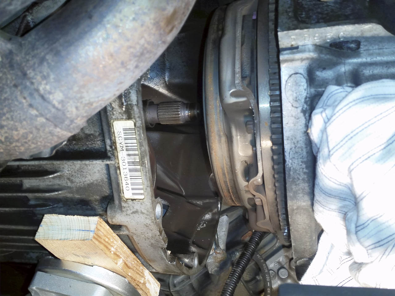
20. Now you can start to wiggle and slide the gearbox away from the engine.There are tabs around the bellhousing to help you, and you can lever them apart with something soft (wood, plastic). Remember it’s only aluminium, so can be damaged easily.
21. Once the shaft is clear of the clutch housing, you can lower the gearbox and roll it backwards out of the way.
22. Finally, evenly loosen the 9 clutch housing bolts (10mm, 12 point heads), in a cross pattern, a little at a time. Once they are removed, the clutch housing and release bearing will fall away from flywheel and the friction plate will drop out. Be ready to catch them.
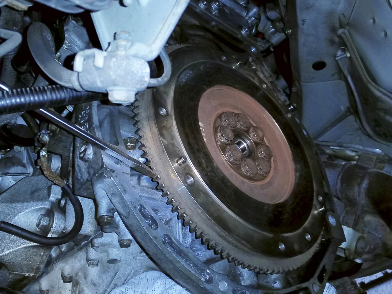
23. If you need to remove the flywheel in order to replace it, or the pilot bearing, you’ll need either a breaker bar (and space below the car to wield it),plus jam a screwdriver between the chassis (use the corner above and to the right of the flywheel) and the teeth of the flywheel, or use a powerful impact driver (mine was 450Nm, my 220Nm driver wouldn’t budge them). There are 8x17mm12 point bolts.
24. To tighten the flywheel bolts (use a torque wrench!), jam a screwdriver on the opposite side of the flywheel teeth.
24. To tighten the flywheel bolts (use a torque wrench!), jam a screwdriver on the opposite side of the flywheel teeth.
25. Reassembly is the reverse of the above steps, as monsieur Haynes says! Use the workshop manual for torque specs. Be careful to align the clutch properly before pushing it together. I aligned the shaft in the middle of the release bearing, checked the alignment of the bellhousing with the engine up/down, left/right and then as I pushed them together, checked the gap between the bellhousing and the engine was even all around. That way, you get it aligned along the same axis.
I hope that helps some people. If you spot any errors, don't hesitate to let me know.Chris


 01-22-2015, 02:02 PM
#6
Thread Starter
Originally Posted by Doyal
That is an awesome guide! And the reason I will pay somebody to change mine when the time comes !! 
 It isn't the most simple of jobs. Needs a bit of effort!
Trending Topics
01-22-2015, 11:37 PM
#8
Thread Starter
Merrell Chameleon Wrap Slam, actually. Comfiest walking/approach shoes I ever had. Sadly worn out and demoted to car fiddling!
The purpose, however, was to show a bit of scale on the length of extensions!
The purpose, however, was to show a bit of scale on the length of extensions!
01-23-2015, 12:17 AM
#10

Nice writh up, but worth adding, whilst it's off grind off the nipple on the slave ball and use urea UHT grease to lube the release fork contact points, and re stuff the selector with UHT grease as it goes back.