When you click on links to various merchants on this site and make a purchase, this can result in this site earning a commission. Affiliate programs and affiliations include, but are not limited to, the eBay Partner Network.
Start by feeding the ECU A & B and C101 connectors of the RSX Harness through the fire wall. The RSX Grommet completely covered my firewall opening, but you could swap the S2000 engine harness grommet for a perfect fit. Route the rest of the wiring under the brake booster and along the firewall. Follow the Engine Wiring Harness diagram from the RSX Service manual and make the following connections: RSX EWH
13. Connect K Series Chassis Adapter S2000 C101 Female plug to S2000 C101 Male plug. Connector K Series Chassis Adapter RSX C101 Female Plug to RSX C101 Male Plug from Engine Harness. Tap the following loose wires from the K Series Chassis Adapter into the 32p A connector on the S2000
a. Fuel - E Plug position 1 (GRN/YEL) = IMO Fuel Pump Relay to S2000 position A15 (GRN/YEL)
b. Fan - C101 Plug Position 4 (GRN) = Radiator Fan to S2000 position A20 (GRN)
c. MIL - E Plug Position 31 (GRN/ORN) = MIL to S2000 position A18 (GRN/ORN)
d. Tach - E Plug Position 27 (BLU) = RPM Output to S2000 position A19 (BLU)
e. Ground – BLK ring terminal bolt to chassis ground
S2000 Chassis Adapter
S2000 A Connector Plug S2000 A Connector Wire Location/Colors
14. Run the O2 Plug from the Chassis Adapter through the firewall.
15. A/C
a. Run wire from A/C Compressor Clutch to ECU connector to pin E18 at the RSX ECU
b. Need to pin and insert into Rywire E Connector
c. Tap B9 BLU/BLK at the RSX ECU to A27 BLU/RED on S2000 32P A connector
16. Coolant Gauge
a. Tap B8 (RED/WHT) on RSX Harness and run wire and tap into S2000 position A1 (YEL/GRN)
17. Plug A, B, E plug into the ECU
I'll take a picture of the final mounting position, shortly.
1. Install AC compressor. Plug ports or loosely install AC hoses. These will need to be modified at an AC shop when the system is filled.
2. Make sure Alternator is connected (ring terminal and plug), but do not bolt into place.
3. Put a new F20 Intake Gasket in place on the Intake adapter and bolt the intake manifold to the head using the supplied bolts (10).
4. Install Throttle Cable.
5. Remove secondary air system. (Optional, but recommended since not operational)
a. Remove Air Control Valve from intake manifold. Block off.
b. Remove vacuum lines. Plug most rearward port on Intake Manifold.
c. Remove Air Control Valve Vacuum Control Solenoid Valve on intake.
d. Remove Air Control Vacuum Reservoir.
e. Remove Air Pump behind front bumper.
f. Remove Air Pump Relay behind front bumper.
g. Remove two large air lines and hard piping.
6. Bolt Alternator into place.
7. Install tensioner pulley bracket.
8. Modify idler pulley bracket (The idler pulley bracket needs to be ground down in the middle to fit the TPS sensor connection when the intake manifold is installed) to fit TPS sensor behind it.
9. Install TPS on Intake Manifold (28 – RSX EWH)
10. Install idler pulley bracket w/ pulley.
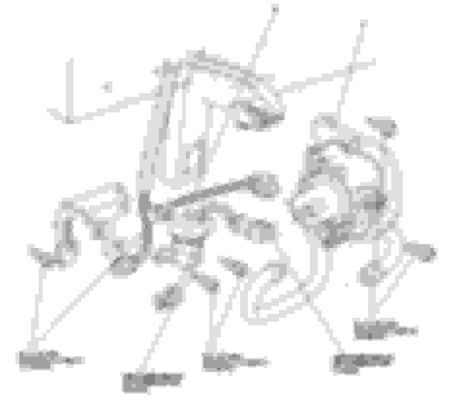
11. Install belt following the routing below. Relieve tension from the tensioner with a 14mm wrench and slip over the tensioner pulley.
12. Install Intake Tubing and Filter. I’m using a 3” to 2.5” Silicone reducer to a 2.5” Aluminum Tubing 90 into a 2.5” to 3.5” Silicone Reducer to the stock filter. This is to clear the belt routing currently. Not sure if a 3” pipe will fit with the current idler location and size. Will update as I test it out because a 3” Intake will be the best for this engine.
13. Make cooling connections for IACV and Throttle Body if you have those lines in place. (I do not)
I am in the process of hooking up AC on my K swap. I jumped from A27, and tapped on to B9 on my RSX Ecu. After I connect E18 to the AC Compressor do I need to set anything special on my ecu? Are you running Kpro?
To clarify your AC compressor wiring.Wire E18 does not go to the compressor clutch directly. It is actually a ground for the AC Compressor clutch relay. You will instead run E18 to A17 on the body harness of the s2000, you will still need to tap A27 onto B9. You will then extend the blue/red wire on the jumper harness to the compressor (Output wire from the AC Compressor Clutch relay).
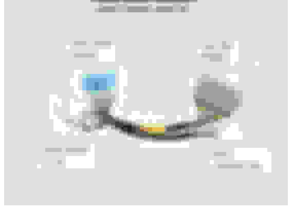
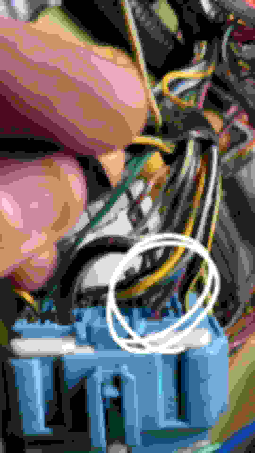
Below is the photo of the wire you need to extend. I am not sure if it has a pin number or not.
To clarify your AC compressor wiring.Wire E18 does not go to the compressor clutch directly. It is actually a ground for the AC Compressor clutch relay. You will instead run E18 to A17 on the body harness of the s2000, you will still need to tap A27 onto B9. You will then extend the blue/red wire on the jumper harness to the compressor (Output wire from the AC Compressor Clutch relay).
Below is the photo of the wire you need to extend. I am not sure if it has a pin number or not.
Hey sorry I didn't see your PM. Glad you got it figured out. I ran a new wire directly from the AC Compressor Clutch(Since my connectors was ripped off) to E18 at the RSX E Connector
Hey sorry I didn't see your PM. Glad you got it figured out. I ran a new wire directly from the AC Compressor Clutch(Since my connectors was ripped off) to E18 at the RSX E Connector
No worries! I had to pin E18 myself as well. I just wanted to clarify where that wire goes from the ECU. Hard to find a solid answer. You want to use the factory relay to send the power to the compressor.
Why K20 and not K24/K20 or am I missing something?
x2 , total waste of time and money just to lose 30 hp , should have fully built 2.6 brian crower stroker , but judging from his front bumper looks like hes a broke ass