When you click on links to various merchants on this site and make a purchase, this can result in this site earning a commission. Affiliate programs and affiliations include, but are not limited to, the eBay Partner Network.
I'm going to start using the following line to let people see where the most recent updates have been made. Look for it in the posts below, it will look something like the following...
************* updated 5/26/03 9:30am
The first couple posts on this thread are going to serve as a consolidation point for all the info that will be accumulated through out the life of this thread and will be fleshed out as progress is made.
Bare with me as I get the skeleton of this thread going, its going to take awhile...
Briefly, the purpose of this thread is to provide details of the brake system I am currently trying to put together. This is primarily a learning experience for me as I have no previous brake system design experience and I expect to incorporate elements as people weigh in on this design process.
This first post is to serve as an overview of the design, its purpose and constraints.
Through much trial a tribulation I've determined that I need a brake system that does not yet exist for the S2K. I have come to realize that my needs from a brake system are on the extreme side to such a degree that I doubt any existing system would be upto the task. Therefore I'm going to learn how to build my own bake system and share the results.
I actually started down this path not long after completing the OpenTrackChallenge. At that point I started looking around to see what options I had available in an over designed brake system. Over designed in this case being an ability to handle a very high heat load.
The primary way to handle a very high heat load in a brake system is to add mass and vented surface area. The various big brake kits I found all attempt to accomplished this through the use of larger diameter rotors. That helps with the mass but it doesn't much improve the surface area as the rotors are still thin, about 1" or less. It seemed to me the best way to increase mass would be to use the additional mass to increase vented surface area. You can do that by increasing the thickness of the rotor instead of its diameter. You can further improve things if you couple that with an increase of diameter. So, an increase in thickness and possibly an increase in diameter should go a long way to taking care of the very high heat load. Another way to help handle a high heat load is through the use of brake pads with greater volume. Thicker pads will help protect a caliper from heat as well as pads with a greater surface area.
So the strategy is to design a system that uses a thicker rotor, thicker pads and possibly a larger diameter rotor.
At this point the constraints on the design come into play. Primarily I want to increase the thickness of the rotor. Ok, how much room is there to squeeze a thick rotor and a caliper that would work with it? Turns out there isn't much room at all. What about rotor diameter? What will fit? Well I'm running custom 18" rims at the track and seeing as I'll be trailering this car from track to track I have no need to worry about fitting stock rims. Though it would be nice if I could. I'm going to leave that option open and primarily concern myself with fitting the 18" rims. If I can get that to work I'll deal with stock rims later. Ok, so the primary constraints are dimensions of depth and diameter. I figure I should deal with the depth issue first and leave the issue of diameter till later. Time to start researching calipers and their dimensions. Turns out some calipers are quite abit thicker(deeper) than others. That variability has to do with 2 things. The thicker the pads its designed to work with the thicker the pistons needed to move the pad towards the rotor thus a thicker caliper. Also, reinforcement of calipers can be accomplished by making them thicker as well. OK, so pad thickness plays into the depth constraint. So with an eye towards caliper thickness its time to choose a couple popular pad sizes and see how they fit into the depth constraints based on the calipers available for those pads.
After a lot of research looking around and taking of measurements it turns out that there are three very popular sizes of pads in use and the calipers that use them are a lot cheaper than the calipers that don't. The small pads are the ones I currently use and just about every caliper maker produces calipers for them. The other two sizes are similarly supported. The mid sized pad is thicker and has a greater surface area than the pad I currently use but its thin enough that there is a good chance a caliper that uses it could fit my depth constraint. The large pad size is completely out of the question. There is no way I could fit a caliper that uses it into the tight space available. So I now have a very strong candidate for a brake pad, now I just need to choose a caliper that will fit these pads and fit in the space needed. Turns out there is one maybe two calipers that will fit, both are inexpensive and readily available they also fit rotors of 1.25" thickness so I order a set of the thinnest calipers. Turns out they also have a lot of features designed to handle high heat loads. Features like stainless steal shielding, high temp O-rings and stainless steal pistons.
Well these calipers come with a couple different piston size setups. Time to figure out what piston sizes I need to make this work correctly. Turns out there are 2 ratios I need to think about one is the hydraulic ratio of master cylinder size to piston area size and the other is the pedal ratio that determines the mechanical advantage at the brake pedal. Since I'm seriously considering going to a 2 master cylinder brake setup I give some thought to removing the vacuum brake booster and utilizing and aftermarlet brake pedal setup. One look under the steering wheel and I don't see how I could possibly fit a pedal assembly in there so I give up on that idea. Now there is only one ratio to worry about. So I spend some time and figure out what the stock hydraulic ratio is. This will serve as a guide to what I should use for caliper piston size as I figure I should keep this as close to the stock ratio as possible. Turns out my current setup is quite aways off from the stock hydraulic ratio. In looking over the available piston setups I see that there are 2 choices that are closer to the stock ratio, one greater and one less than the stock value. I'm not sure which is the better side to error on so I order at set of each size. It will likely turn out the the smaller piston size is the correct way to go. Further calculations show that when they are configured as two front calipers on one master cylinder the hydraulic ratio is very close to the stock value. A larger diameter rotor and the extra mechanical advantage it provides will come into play here as well. I figure its best to leave a couple options open.
Calipers in hand its now time to see if these suckers will actually fit. So its also time to download a cad program learn how to use it and draw up some caliper brackets. With the drawing and some aluminum from a HW store I come up with a mockup of the bracket I designed. I then proceed to use precision washers to space out the mockup bracket and determine the proper offset to get it to fit properly. I had a good idea of were to start based on drawings and measurements I had created earlier. With the offset determined its now time to determine the offset of the rotor hat and get them ordered, one set for each of the two styles of rotor I'm goin to try out. I now have real brackets machined up by IrishStook and now I'm just waiting on the hats from Essex.
Well that is pretty much where I'm at right now.
Next, I'll be receiving the dual master cylinder mount and 2 master cylinders. I just need to come up with a cad drawing of an adapter to mount it to the vacuum booster. I'll remove the ABS system and take a look at rewireing it from a diagonal circuit actuation to a front and rear actuation setup. Either way its time I learned how to threshold brake.
I see 2 phases to this. The first phase will be to get the new calipers and rotors working with out any changes to the stock master cylinder or ABS. Phase two will see the implementation of a dual master setup and removal of the ABS. BTW, The dual master setup will allow for the fine adjustment of front to rear brake bias.
************* updated 5/26/03 9:30am
I've been asked to look into upgrading the rear brake system. See below for some caliper calculations regarding this. I had not originaly planed on doing this but the more i think about it the more I like the idea. Especially when considering that I've been going thru rear pads much quicker now that I've been using the Big Ass Active Aero Wing. I think a rear upgrade will help to offset the extra work the rear brakes will see when they are coupled with improved front brakes. In going with new rear calipers we have a couple popular rotor sizes to work with. By far the most popular is an 11.75" diameter 0.81" thick vented rotor. Its thicker than the stock .5" rotors and is larger than the 11" stock diameter. Those features should improve the rear braking ability and greatly improve its ability to take an increased heat load.
At this point I'll need to check clearance issues in fitting a larger rotor and caliper as well as how or if to mount a mechanical spot caliper to implement an E-brake function.
This second post will list the specs of the various elements that make up the design as it currently exists as well as any variations on the design.
Phase1:
Calipers, At this point I'm unsure which piston sizes to go with as the 2 phases may have different requirements. Both calipers are meant for 1.25" thick rotors. The first set have 4 X 1.38" pistons, the second set have 2 X 1.62" and 2 X 1.75" pistons. Outlaw 4000 caliper. The 2 part #s I have are 170-1780/1785 and 170-1800/1805.
I have ordered 2 different sets of rotors as I'm not sure which will work out better. Both are 1.25" thick and the Wilwood GTs are 12.9" diameter while the Coleman are 13.0" diameter. Wilwood GT series rotor part # 160-4564/4565
I have ordered 1 set of rotor hats to fit the Coleman rotors from Essex Parts Service.
Well it turns out that this was probably a mistake. Essex is going to take 3 weeks to get the parts made and they'll be rather expensive. I canceled the second order for hats that will fit the Wilwood rotors.
In my previous hunt for rotor hats to fit my needs I talked to a couple different people that frequent this board but I never got anywhere with that. They kept on dropping the ball. I have since located this place, http://www.precisionbrakes.com/ , by a recommendation from airsport. Thanks!. After a few minutes of looking they were able to locate a Wilwood part with the need specs. They have been ordered and should be here early next week.
This post will contain all the pictures associated with the design. I may move this to a separate thread or simply provide links to the pictures if having them here becomes troublesome.
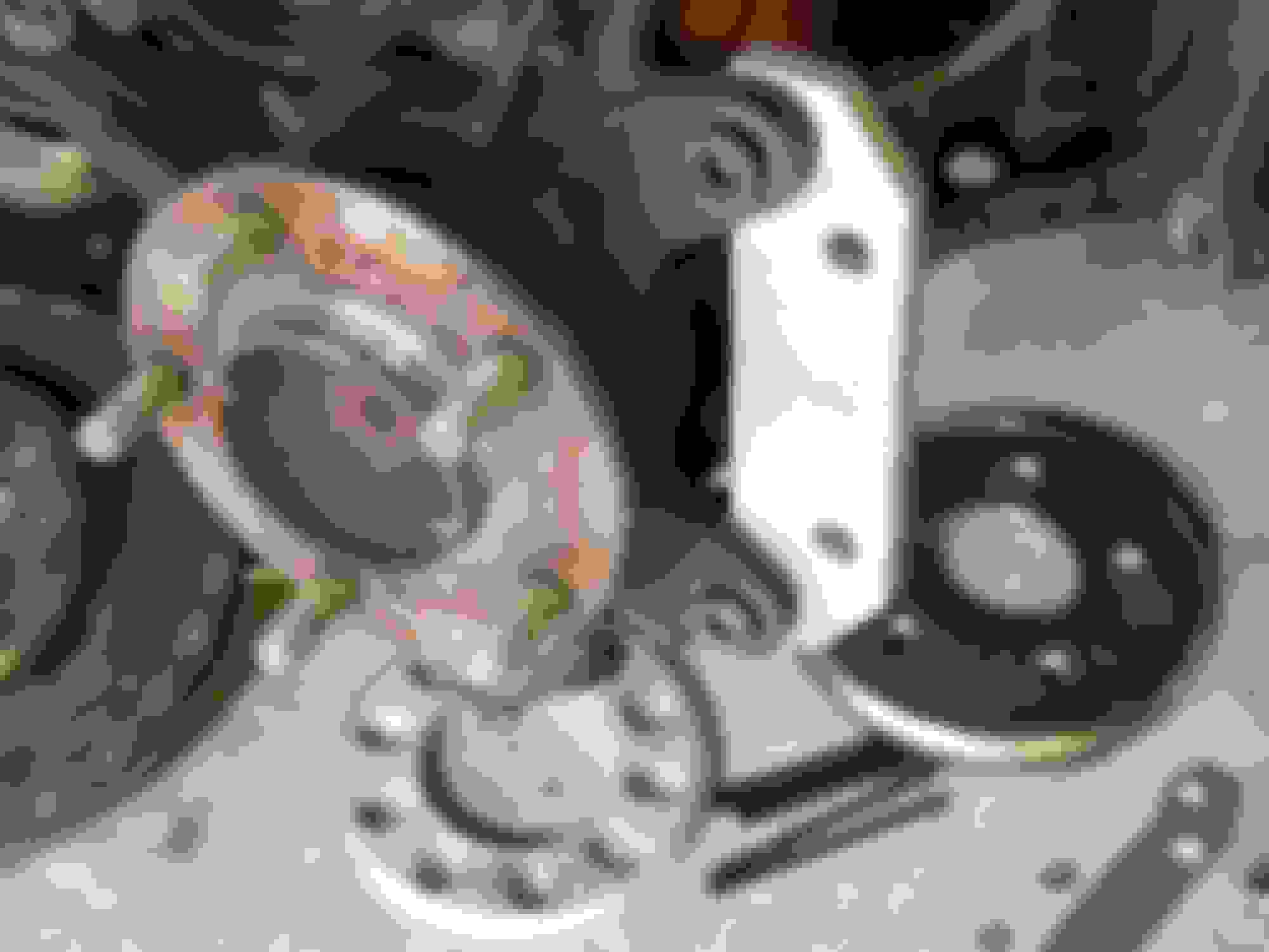
Here are a couple pics showing the actual bracket to be used in place.
In the following photo note the width of the space between the caliper halves and how the inboard half lines up with the bracket mounting bolts. You should notice that the Spindle to Bracket bolt head actually lies within the rotor. Keep in mind that the rotor is 1.25" thick
Design notes and calculations used to come up with the design.
Hydraulic Ratio calculations for various setups.
A = pi * r^2
Hydraulic ratio = piston area driven by master cylinder / master cylinder area
Note, in 4 piston calipers area is determined by the pistons on only one side of the caliper.
Stock front: 1 X 2 1/8" diameter piston = 3.546 sq"
Pinnacle front: 2 X 1.75" diameter pistons = 4.810 sq"
Outlaw 4k: 1 X 1.75" + 1 X 1.62" diameter pistons = 4.466 sq"
Outlaw 4k: 2 X 1.38" diameter pistons = 2.99 sq"
Stock rear: 1 X 1.575" diameter piston = 1.948 sq"
The stock master cylinder is a tandem 1" diameter setup. This means that there are 2 cylinders one behind the other each with a diameter of 1". Each one of these drives one of the two diagonal brake circuits. The ABS system keeps these two diagonal circuits separate.
In figuring out the stock hydraulic ratio we'll look at one of the two identical diagonal circuits. Each one of these circuits drives one front and one rear caliper.
This gives us a stock hydraulic ratio:
Stock diagonal circuit piston area / Stock master cylinder area = 5.494 sq" / 0.785 sq" = 7:1
I figure this 7:1 ratio is what i should shoot for in any design i come up with. Unfortunately this is only an assumption on my part and i'd be interested to hear different points of view on the matter.
Now for a couple comparison setups.
My current setup is a pinnacle system up front, stock rear and stock master cylinder.
Diagonal circuit piston area: Pinnacle front piston area + stock rear piston area = 4.810 sq" + 1.948 sq" = 6.758 sq"
This gives me a hydraulic ratio of
Pinnacle hydraulic ratio: Pinnacle diagonal circuit area / stock master cylinder area = 6.758 sq" / 0.785 sq" = 8.6:1
Note that as the ratio increases the pressures attainable in the hydraulic line also increases. It also means that with the pedal ratio unchanged you will need to move the pedal further to attain the same hydraulic pressure. I think this explains the deep pedal that i suffer from with my current setup. It might also explain some of the seal problems i've had, possibly being due to increased hydraulic pressure. At 8.6:1 we are looking at a 23% increase over the stock ratio of 7:1.
At discovering this i was curious as to what the stock caliper piston diameters works out to if it were a 4 piston caliper.
For that we take the front piston area and divide by 2 to get the area of one of four pistons. Remember that only 2 of 4 pistons are used when getting the total piston area of a 4 piston caliper. We then derive the diameter from the area of one of the pistons.
Stock front piston area / 2 = 3.546 sq" / 2 = 1.773 sq"
Then from A = pi * r^2 we get the diameter
d = 2 * sqrt(A/pi) = 2 * sqrt(1.773 / 3.1415...) = 1.502"
So a 4 piston caliper should have 4 X 1.5" pistons if you want to keep the stock hydraulic ratio of 7:1.
Ok, i have 2 new sets of calipers here with different piston sizes. Lets see what hydraulic ratio they work out to when used with the stock master cylinder.
First of the Outlaw 4K with 1.75" and 1.62" pistons.
Outlaw diagonal circuit area = OL piston area + stock rear piston area = 4.466 sq" + 1.948 sq" = 6.414 sq"
This gives a hydrauic ratio of
Outlaw diagonal circuit area / master cylinder area = 6.414 sq" / 0.785 sq" = 8.17:1
This Outlaw hydraulic ratio of 8.17:1 is 16.7% greater than the stock ratio of 7:1. That gets us closer to stock but still quite a ways off from 7:1.
Next we'll look at the Outlaw 4k with 1.38" pistons.
Outlaw diagonal circuit area = Outlaw piston area + stock rear piston area = 2.99 sq" + 1.948 sq" = 4.938 sq"
This gives us a hydraulic ratio of
Outlaw diagonal circuit area / master cylinder area = 4.938 sq" / 0.785 sq" = 6.29:1
This Outlaw hydraulic ratio of 6.29:1 is 90% of the stock value of 7:1
Note that with this value lower than stock it means that you have to press the brake pedal harder in order to generate the same hydraulic pressure as a stock system. It also means that you dont have to push the pedal as far in order to acheive that pressure. In other words you end up with a stiffer brake pedal that requires more effort.
I wasnt sure which side i should error on so i went ahead and ordered both sets of calipers. Like i said before i think the smaller piston sizes will ultimately work out better.
In conceptualizing this system i was pretty sure i would want to make it a dual master cylinder setup with one front circuit and one rear circuit instead of the diagonal circuits of the stock setup.
There are a couple different ways to accomplish this. One way would be to remove the ABS and re-hose the stock MC to create separate front and rear circuits. Then you could add a proportioning valve to the new rear circuit to help make fine adjustments to the brake bias. The problem with this option is that you are stuck with a 1" MC for the front and the rear.
It might also be possible to retain the ABS with such a setup but it would require rewiring the ABS actuator and swtching around 2 of the brake lines. I'll look into actually doing this when i eventualy get the ABS unit out of my car.
Another alternative would be to remove the stock MC and replace it with side by side dual master cylinders. Such systems are much easier to balance front to rear through the use of different sized MCs and with a simple twist of a knob you can make fine adjustments for varing track conditions through the use of the integrated balance bar. The balance bar allows you to vary how the pedal effort is distributed to each of the master cylinders by making adjustments to the knob. When in the neutral position the force on each MC is equal and when adjusted clear to one side or the other it produces 2 times as much force on one MC as the other.
Since i decided to go with the side by side dual master cylinder setup for phase two lets take a look at some of the calculations involved.
In going from a diagonal setup to a front and rear setup it becomes apparent that different MC sizes are going to be needed between front and rear if we are going to maintain the stock hydraulic ratio of 7:1. Again, it is only an assumption on my part that this is the correct thing to do. At this point we need to figure out what MC size will give us a 7:1 hydraulic ratio for the front and which MC size will do so for the rear. So we know what Hydraulic ratio we want and we know the piston area involed se we solve for the MC size.
Master cylinder area = driven piston area / Hydraulic ratio.
Master cylinder diameter = 2 * sqrt( driven piston area / (Hydraulic ratio * pi))
In this case for the front circuit we'll look at the 1.38" outlaw calipers first.
The driven piston area is 2 X the area of one Outlaw caliper as we have two front calipers being driven by one MC.
Driven front piston area = 2 X 2.99 sq" = 5.98 sq"
Front MC diameter = 2 * sqrt( 5.98 sq" / (7 * 3.1415...)) = 1.043"
1.043" is very close to the popular 1" MC size so we'll choose to use it. Now we'll figure out what the actual Hydraulic ratio is based on a 1" MC size.
Front Hydraulic ratio = Front piston area / MC area = 5.98 sq" / 0.785 sq" = 7.6:1
That 7.6 hydraulic ratio will make for a slightly soft brake pedal, i may bump the size of the front MC up to 1 1/8" if its too soft.
And now for the rear circuit.
The driven piston area is 2 X the area of one stock rear caliper.
Driven rear piston area = 2 X 1.948 sq" = 3.896 sq"
Rear MC diameter = 2 * sqrt( 3.896 sq" / (7 * 3.1415...)) = 0.842"
0.842" = 13.47/16" so its very close to being 13/16" a popular MC size. If we go with a 13/16" MC for the rear that will give us a hydraulic ratio of...
Rear hydraulic ratio = rear piston area / rear MC area
Rear MC area = pi * r^2 = pi * (.8125 / 2)^2 = .518 sq"
This 7.5:1 value for the rear is very close to the 7.6:1 value of the front. Hopefully this will mean that the system will be well balanced from the get go.
I'm also curious if the 1.75" + 1.62" calipers will work in a side by side dual MC setup. Lets check it out.
In this case the Driven piston area of the front circuit will be equal to 2 X 4.466 sq" = 8.932 sq" and assuming a hydraulic ratio of 7:1 that gives us a MC diameter of...
Front MC diameter = 2 * sqrt( 8.932sq" / (7 * 3.1415...)) = 1.275"
Crap. I've never seen a MC with a diameter of 1.25", the biggest i've ever seen is 1.125". Looks like i'll be using the 1.38" piston calipers with my dual MC setup.
************** updated 5/25/03 9:30am
I've been asked by a couple people to look at upgrading the rear brake setup and the more i think about it the more i like the idea. Here are some prelimimary calculations to get us started.
The stock rear caliper has a piston Diameter of 1.575" for a piston area of 1.948 sq". If the caliper had 4 pistons each would be...
piston diameter = 2 * sqrt( piston area / pi ).
The piston area in this case is the 1.948 sq" / 2 = 0.974 sq". Remember there are 2 pistons in a four piston caliper that go towards the total piston area.
Al, i'm not going to sell anything. This is simply a learning experience for me and hopefully others. The way i look at it is i could spend $2k on a new off the shelf system and hope that it will meet my needs and not learn anything in the process. Or, i could spend that or less on something of my own design that i know should meet my needs and learn every little detail of how it works in the process.
 05-18-2003, 01:20 PM