
LoveFab turbo kit

Thread Starter
Moderator

Joined: Oct 2000
Posts: 30,809
Likes: 15
From: Sydney
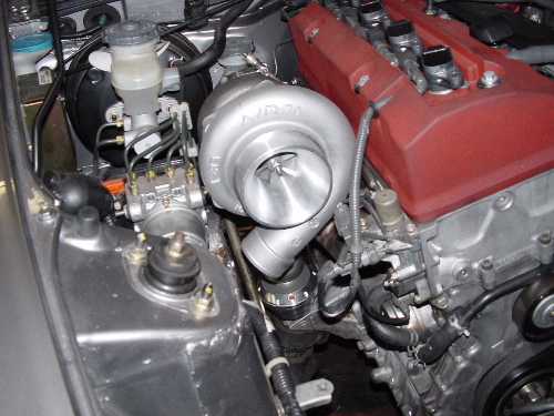
I thought I would start a thread about installing and running the LoveFab turbo kit.
My car is RHD so this was pretty experimental. That said, everything fits fine so far.
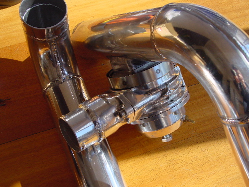
I have most of the parts ready to go and will be installing this weekend. I did my own IC and charge piping.
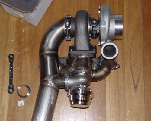
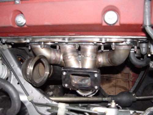
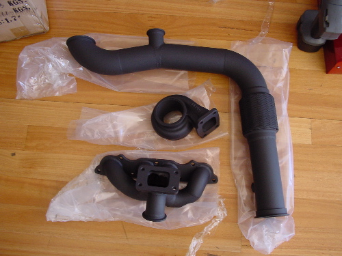
I have had my turbine housing, manifold and downpipe ceramic coated. I also had my manifold machined flat as it was warped.
I am using a Turbonetics Godzilla BOV but am routing the outlet back to the intake for a quieter system.
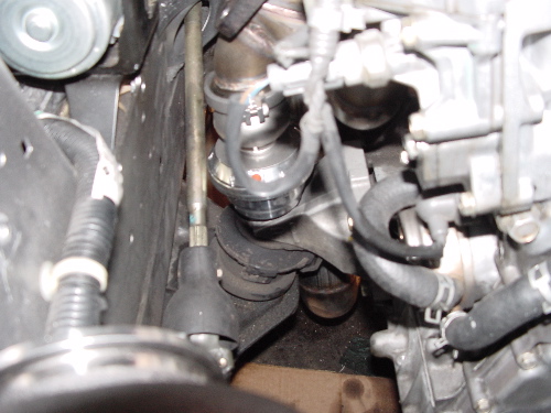
In lieu of instructions I am interested in pictures of the oil feed and drain and the water circuit. If no one else has done them I will nut them out this weekend and post pictures.
My car is RHD so this was pretty experimental. That said, everything fits fine so far.
I have most of the parts ready to go and will be installing this weekend. I did my own IC and charge piping.
I have had my turbine housing, manifold and downpipe ceramic coated. I also had my manifold machined flat as it was warped.
I am using a Turbonetics Godzilla BOV but am routing the outlet back to the intake for a quieter system.
In lieu of instructions I am interested in pictures of the oil feed and drain and the water circuit. If no one else has done them I will nut them out this weekend and post pictures.
Thread Starter
Moderator
Joined: Oct 2000
Posts: 30,809
Likes: 15
From: Sydney
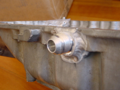
Oh, I also baffled my sump whilst installing the return.
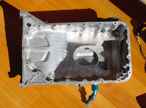
The baffle is level with the base of the sump. I haven't done final fitting yet nor drilled a hole for the dip stick but I will do them this weekend. It's only 2mm Al so adjustments will be pretty easy.
The baffle is level with the base of the sump. I haven't done final fitting yet nor drilled a hole for the dip stick but I will do them this weekend. It's only 2mm Al so adjustments will be pretty easy.


Registered User

Joined: Jul 2004
Posts: 8,796
Likes: 2
From: San Diego, Wess-Side!!
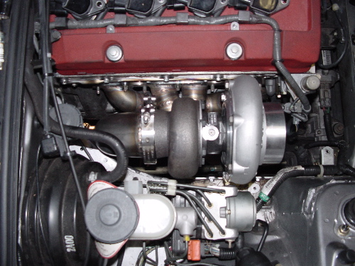
Liemoanh's kit is pretty much done... I helped install the manifold/blower/wastegate... fitment was a bitch!
The clearance on the wastegate side is like NONE.
I'll let him chime in.......but he's pretty much done. Last I talked, the mounting for the Intercooler didn't allow it to sit high enough...
The clearance on the wastegate side is like NONE.
I'll let him chime in.......but he's pretty much done. Last I talked, the mounting for the Intercooler didn't allow it to sit high enough...
Thread Starter
Moderator
Joined: Oct 2000
Posts: 30,809
Likes: 15
From: Sydney
I had trouble test fitting the down pipe to the turbo and wastegate but Tinker told me to loosen everything off (wastegate collar and turbo-manifold bolts) and it all went together fine. I expect I will have the same issue now that the mating flanges are coated and might dremel off the surfaces first.
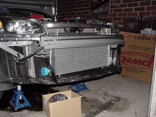
My intercooler is a PWR tube and fin 600x300x76. I spent ages making up the brackets from angle steel. It basically hangs from the threaded stubs at the top. The bottom mount just holds it out at the correct angle. The top of the IC is behind the bumper support. I may have to channel more air up to it. That said, I am very impressed with how well it fits.
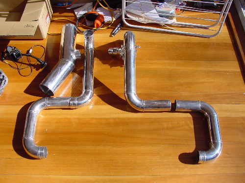
All the IC piping was cut here and mocked up by holding it in place. Once I had the four sections worked out I strung them together on string and used a permanent marker to show which pieces joined to which and at what orientation. I then took them out to the welder and he spent 10 hours welding them together. I hope they fit. Most of them look pretty good by I think the pipe connecting to the throttle body will hit the bonnet. May need to be cut and angled.
My intercooler is a PWR tube and fin 600x300x76. I spent ages making up the brackets from angle steel. It basically hangs from the threaded stubs at the top. The bottom mount just holds it out at the correct angle. The top of the IC is behind the bumper support. I may have to channel more air up to it. That said, I am very impressed with how well it fits.
All the IC piping was cut here and mocked up by holding it in place. Once I had the four sections worked out I strung them together on string and used a permanent marker to show which pieces joined to which and at what orientation. I then took them out to the welder and he spent 10 hours welding them together. I hope they fit. Most of them look pretty good by I think the pipe connecting to the throttle body will hit the bonnet. May need to be cut and angled.

Trending Topics
Thread Starter
Moderator
Joined: Oct 2000
Posts: 30,809
Likes: 15
From: Sydney
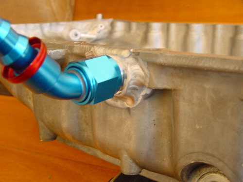
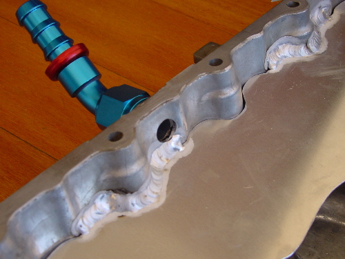
Are you asking about the baffle or the return spigot? Both are welded. The baffle is welded at sevaral point around the side. The oil return spigot was welded to the side and then drilled through. It's pretty high and I may have some clearance problems but we'll see on the weekend.

Registered User
Joined: Oct 2004
Posts: 697
Likes: 1
From: Traverse City, Michigan
Its all definately a tight package!!!
Just about to trip 13,000 miles since the end of January. As for the manifold flange being warped, its a natural tendancy when it pops out of the jig. We cut expansion slots so it easily bolts flat to the head, as well as to allow things to move without breaking/loosening head studs(experienced this during the first dyno session, was fixed directly after, has been since). Once the manifold gets hot a few times, if its ever removed from the head again, it comes off perfectly flat.
JakubS2000 is running, but I fear there are some wiring differences between the cars because they cannot get their UEGO and AEM EMS to sinc together(and they ARE plugged into the correct wire). It may have been a programming error, but itll be another two weeks till we find out as Jakub is out of town.
Two more kits being shipped out today, one will be pushing the base turbo pretty high
Cthree, get me that sponsor Email!!!