
My Vortech S/C install guide!

Thread Starter
Member

Joined: Apr 2004
Posts: 33,838
Likes: 23
From: Sunshine Coast - England UK
Hi all,
I did this diary a while back, original thread is here:
https://www.s2ki.com/forums/index.ph...ic=325803&st=0
Hopefully this thread will help anyone looking to fit a Vortech S/C, as the vortech guide isnt that great.
Basically I never finally put the belt on for a few reasons, and its all removed now - but hopefully if nothing else this will help others doing it. I found XVipers thread a real big help when doing mine, but hopefully the extra pics here will help! Some of it might not read too well because it was a day by day diary - but there we go! Also note this is a RHD car
MB
Right, its Friday and none of my mates are going out so I thought I would begin a long term post into the trials and tribulations of a Vortech install.
Ive had the car 6 months now and really love it. My only gripe is that I love performance modding, and I hit a brick wall with this straight away. N/A mods are stupidly pricey, and while I envy people for going down this route (takes a lot of thought) its not for me.
Here is where I looked into S/C's, got scared off, and came back again
Spent a lot of time on the US forum as it would appear you are nobody unless you have 6 turbo's and a shot of nitrous Those boys dont do thing by halves. So, as I normally do, I spent a few months working out how the cars's ECU and engine worked, and what S/C I wanted. I really wanted the Comptech S/C as it didnt require any drilling into the oilpan for return. But... a Vortech came along at a great price (Thanks Simon ) and I had to have it. Bit earlier than I wanted but I couldnt miss out.
Picked the kit up a few weeks back and have been busy listing a cunning plan before installing it. Its not as simple as bolting it on....
You need to consider:
New plugs and what type (gap is different for S/C)
New oil (its working harder and a bit hotter!)
More tolerant gearbox oil (as above)
Getting all the ECu wiring diagrams together
Insurance (incidetally its only
I did this diary a while back, original thread is here:
https://www.s2ki.com/forums/index.ph...ic=325803&st=0
Hopefully this thread will help anyone looking to fit a Vortech S/C, as the vortech guide isnt that great.
Basically I never finally put the belt on for a few reasons, and its all removed now - but hopefully if nothing else this will help others doing it. I found XVipers thread a real big help when doing mine, but hopefully the extra pics here will help! Some of it might not read too well because it was a day by day diary - but there we go! Also note this is a RHD car
MB
Right, its Friday and none of my mates are going out so I thought I would begin a long term post into the trials and tribulations of a Vortech install.
Ive had the car 6 months now and really love it. My only gripe is that I love performance modding, and I hit a brick wall with this straight away. N/A mods are stupidly pricey, and while I envy people for going down this route (takes a lot of thought) its not for me.
Here is where I looked into S/C's, got scared off, and came back again
Spent a lot of time on the US forum as it would appear you are nobody unless you have 6 turbo's and a shot of nitrous
Those boys dont do thing by halves. So, as I normally do, I spent a few months working out how the cars's ECU and engine worked, and what S/C I wanted. I really wanted the Comptech S/C as it didnt require any drilling into the oilpan for return. But... a Vortech came along at a great price (Thanks Simon ) and I had to have it. Bit earlier than I wanted but I couldnt miss out.Picked the kit up a few weeks back and have been busy listing a cunning plan before installing it. Its not as simple as bolting it on....
You need to consider:
New plugs and what type (gap is different for S/C)
New oil (its working harder and a bit hotter!)
More tolerant gearbox oil (as above)
Getting all the ECu wiring diagrams together
Insurance (incidetally its only
Thread Starter
Member
Joined: Apr 2004
Posts: 33,838
Likes: 23
From: Sunshine Coast - England UK
So what's the idea behind it?
Well, A S/C is driven off an extra pulley, via a belt. Its basically an air compressor or turbine, which compresses air sucked up by the intake, and feed this into the engine. Simple theory is that the more air you can get in, the more fuel you can mix with it to increase combustion. And this means more power!!!!
The reason I like S/C is that its simpler than a turbo (not as efficient) and keeps the VTEC character of the car due to its power being linear with the RPM's
So what's in the kit?
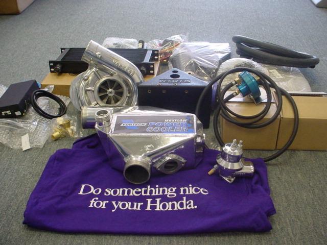
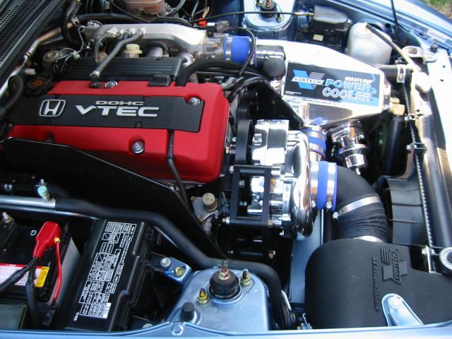
Hopefully when finished it will look like this:
And hopefully it will do this :
http://videos.streetfire.net/Player.aspx?f...CC48F6&kw=3&p=2
MB
Well, A S/C is driven off an extra pulley, via a belt. Its basically an air compressor or turbine, which compresses air sucked up by the intake, and feed this into the engine. Simple theory is that the more air you can get in, the more fuel you can mix with it to increase combustion. And this means more power!!!!
The reason I like S/C is that its simpler than a turbo (not as efficient) and keeps the VTEC character of the car due to its power being linear with the RPM's
So what's in the kit?
Hopefully when finished it will look like this:
And hopefully it will do this
:http://videos.streetfire.net/Player.aspx?f...CC48F6&kw=3&p=2
MB
Thread Starter
Member
Joined: Apr 2004
Posts: 33,838
Likes: 23
From: Sunshine Coast - England UK
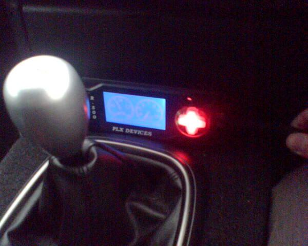
Right, got the PLX wideband mostly installed today. I wired in the power and earth to the ECU, then wired in the main signals, Speed and Knock input from the factory sensors, and AFR will go in once the actual wideband sensor is installed. This is on a separate cable, as it replaces the stock narrowband sensor. Didn
Thread Starter
Member
Joined: Apr 2004
Posts: 33,838
Likes: 23
From: Sunshine Coast - England UK
I got the Wideband lambda probe installed and fitted the resistors that need to make the car run correctly and no CEL's etc. Its worth re-itterating at this point that the wideband is by no means essential, but for me its quite important and its what's been holding up the rest of the S/C install.
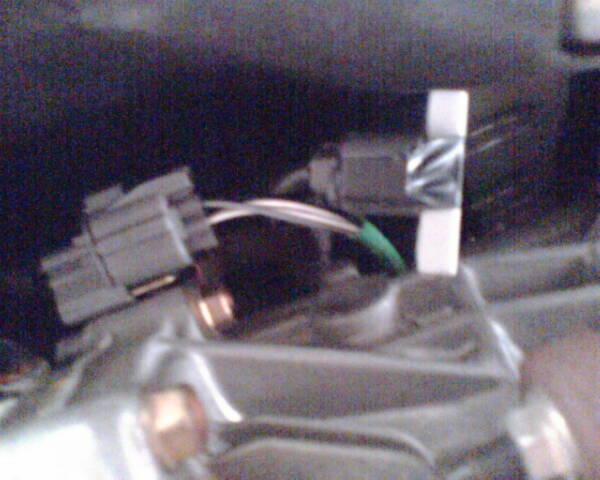
Right, first was to find and unbolt the primary lambda sensor. Found it easy enough but the connector plug was a bugger to get undone!
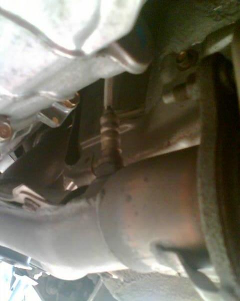
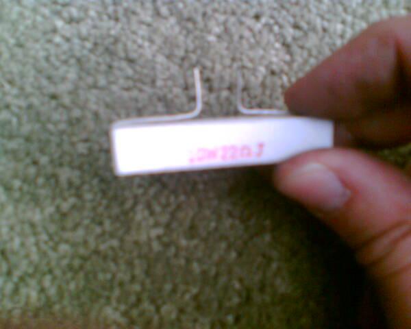
Once disconnected I put the new Wideband in. I also decided to put the 20 ohm 10W resistor into the old lambda plug, that goes back to the ECU. This is needed to stop you getting a CEL, by completing the heater circuit. I modified the resistor a bit
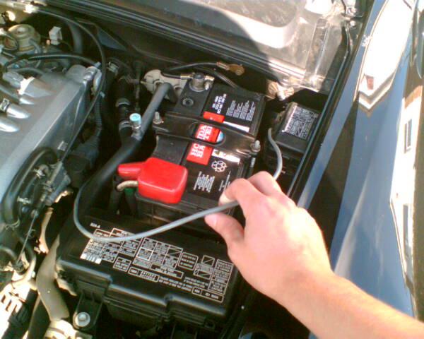
Once installed I ran the new wideband lead up through the engine bay (choosing a nice safe route)
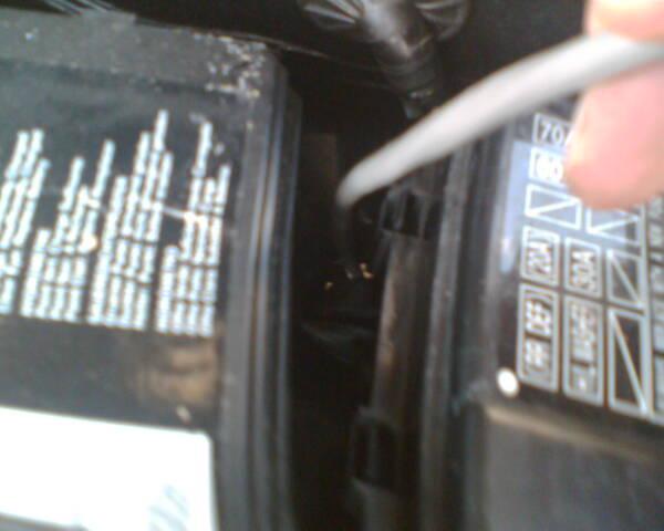
Then threaded the connector through the bulkhead. You can just about see it in this pic and its the hole where all the ECU wires go through.
Did some logging sessions to record the AFR and Knock so will post these up when ive saved them to JPEG. I can then see how the car is running compared to when the S/C is on
The car actually feels much smoother now, with the simulated output from the wideband going into the ECU, instead of the old sensor. Bonus!
Edit - forgot to add that after some logging I cracked on with the fuel pump and got that done - a bit tricky and smelly! Will report back on that later, uploading pics is a pain in the butt!
MB
Right, first was to find and unbolt the primary lambda sensor. Found it easy enough but the connector plug was a bugger to get undone!
Once disconnected I put the new Wideband in. I also decided to put the 20 ohm 10W resistor into the old lambda plug, that goes back to the ECU. This is needed to stop you getting a CEL, by completing the heater circuit. I modified the resistor a bit
Once installed I ran the new wideband lead up through the engine bay (choosing a nice safe route)
Then threaded the connector through the bulkhead. You can just about see it in this pic and its the hole where all the ECU wires go through.
Did some logging sessions to record the AFR and Knock so will post these up when ive saved them to JPEG. I can then see how the car is running compared to when the S/C is on
The car actually feels much smoother now, with the simulated output from the wideband going into the ECU, instead of the old sensor. Bonus!
Edit - forgot to add that after some logging I cracked on with the fuel pump and got that done - a bit tricky and smelly! Will report back on that later, uploading pics is a pain in the butt!
MB
Thread Starter
Member
Joined: Apr 2004
Posts: 33,838
Likes: 23
From: Sunshine Coast - England UK
Next the aftercooler install!
Removed the front bumper to fit the aftercooler matrix, coolant pump and coolant box. Getting the bumper off was ok, bit time consuming as there are about 20 fasteners / bolts holding it on. then it started to rain a bit! Carried on anyway
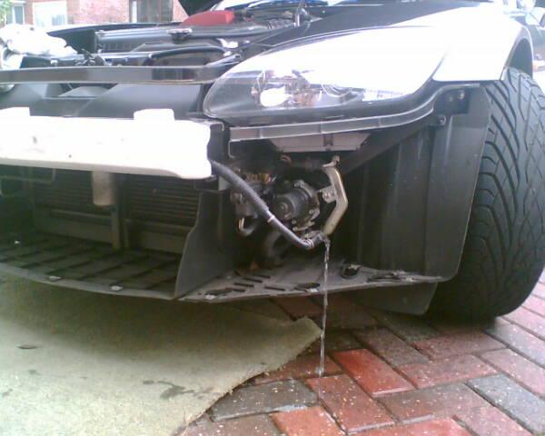
Note the washer fluid pouring out the headlamp washer pipes Tied these off to stop it flooding my work area!
Had to loosen the undertray to allow the new radiator to slip up past the AC pipe at the top. Its a VERY tight fit. Got it in and routed the hoses.
Next step is to add plumb in the ccolant box in the drivers side wing. This involves mounting it to the side divider and cutting a small hole to route the pipe through to the radiator area, where the new pump will live.
Completed that then fitted the coolant pump along the bottom of the main radiator. Led the +12v feed wire from the pump, and the coolant hoses up to the engine bay and tucked them away for now, until the main cooler goes in
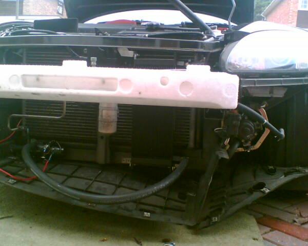
Bumper back on and all done! This was trickier than I thought, but not too hard. Bit of drilling for mounting the bits but NO major surgery which is great for when / if I come to remove it.
PS - I shortened the main hose in the pic above afterwards, and secured the pump with the discharge pointing up as per instructions.
MB
Removed the front bumper to fit the aftercooler matrix, coolant pump and coolant box. Getting the bumper off was ok, bit time consuming as there are about 20 fasteners / bolts holding it on. then it started to rain a bit! Carried on anyway
Note the washer fluid pouring out the headlamp washer pipes
Tied these off to stop it flooding my work area!Had to loosen the undertray to allow the new radiator to slip up past the AC pipe at the top. Its a VERY tight fit. Got it in and routed the hoses.
Next step is to add plumb in the ccolant box in the drivers side wing. This involves mounting it to the side divider and cutting a small hole to route the pipe through to the radiator area, where the new pump will live.
Completed that then fitted the coolant pump along the bottom of the main radiator. Led the +12v feed wire from the pump, and the coolant hoses up to the engine bay and tucked them away for now, until the main cooler goes in
Bumper back on and all done! This was trickier than I thought, but not too hard. Bit of drilling for mounting the bits but NO major surgery which is great for when / if I come to remove it.
PS - I shortened the main hose in the pic above afterwards, and secured the pump with the discharge pointing up as per instructions.
MB
Trending Topics
Thread Starter
Member
Joined: Apr 2004
Posts: 33,838
Likes: 23
From: Sunshine Coast - England UK
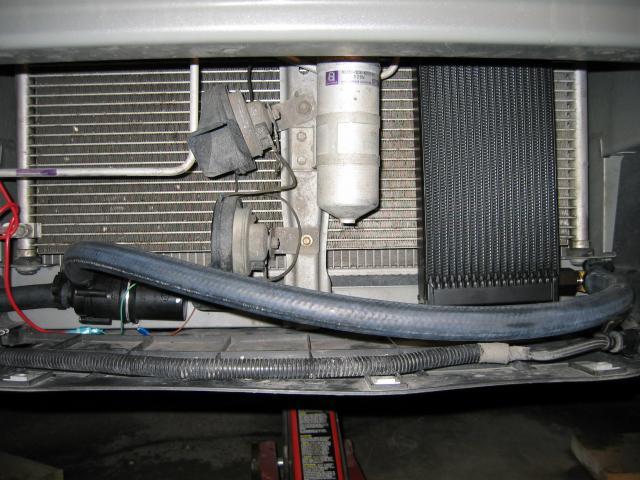
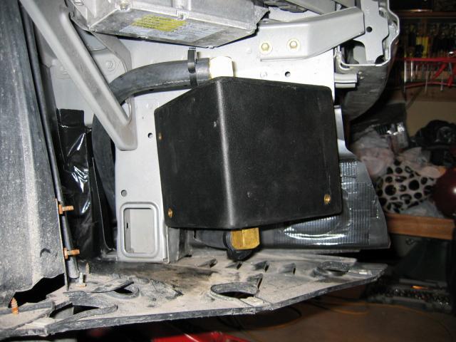
Here's some close up pics of the rad / pump and coolant box for info. Not off my car but mine now looks the same!
Ive refitted ALL the plastic fasteners with some beefy jubilee clips and screwed everything back in place! I now have 2 open ended pipes in the engine bay and they will stay like that until the aftercooler unit goes in place, which can only go in once the main charger is installed!
Might put the S/C pulley on today too
Update later!
MB
MB
Thread Starter
Member
Joined: Apr 2004
Posts: 33,838
Likes: 23
From: Sunshine Coast - England UK
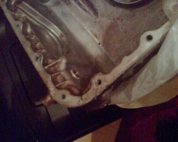
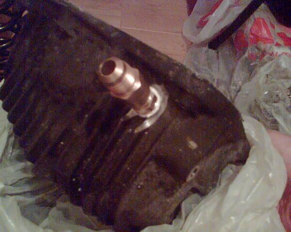
Got my spare oil pan drilled and tapped yesterday, not welded it yet as the lads at work couldn't do aluminium. Just got to get the Honda sealant and I will have a crack at swapping the pan Got to give it a total clean up to make sure there isnt the slightest bit of debris in the pan.
This is probably the bit that will scare most off doing the install, but its really quite simple. As long as you get a v good seal on the thread and the pan mating face, all should be well. I will just check it very regular once its on and if it doesnt leak early on, its not really going to start leaking.
Dodgy camera phone pics
MB
Got to give it a total clean up to make sure there isnt the slightest bit of debris in the pan.This is probably the bit that will scare most off doing the install, but its really quite simple. As long as you get a v good seal on the thread and the pan mating face, all should be well. I will just check it very regular once its on and if it doesnt leak early on, its not really going to start leaking.
Dodgy camera phone pics
MB
Thread Starter
Member
Joined: Apr 2004
Posts: 33,838
Likes: 23
From: Sunshine Coast - England UK
Fuel Pump!
Right, finally got the fuel pump pics uploaded! I put plenty of detail into this as it can be seen as tricky. Pretty straight forward tbh!
First of all, pull out fuse no 12 under in the fuse box the steering wheel. This is the fuel pump fuse. Then try and start the engine twice. This sucks all the fuel out the lines - hopefully! Then open the fuel cap to release any pressure, and replace.
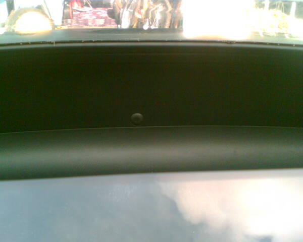
Ok, the fuel pump lives behind the boot panel where the spare wheel lives, so first step is open the boot! Then remove the spare wheel panel.
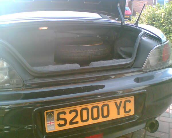
The pump is to the left, out of shot.
Need to remove the rear tray behind the hood, as it creates access to the top of the fuel pump. This is a bit of a bastard as you have to work kneeling on the seat and reaching between the roll hoops. The black plastic clips you can see have a little round bit in the middle. Push these in and you can then pull out the whole clip. The hardest ones are behind the seat area as you cant see what you're doing! There are 3 white ones which have to be pushed up through from the boot. Dont try and prise them up.
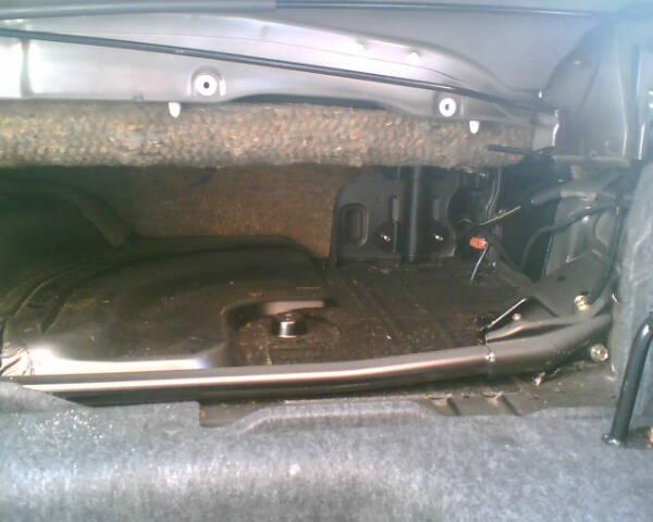
Remove the panel below, through the boot.
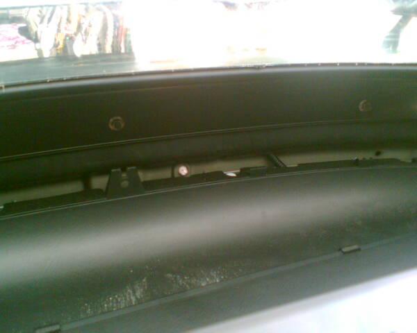
Remove 3 screws to uncover the fuel lines and pump lid. Push the clips in on the fuel hoses and pull off the hose, and unplug the connector. The return on the right wont spray you, but the other probably will! Use a rag around it to keep it all contained.
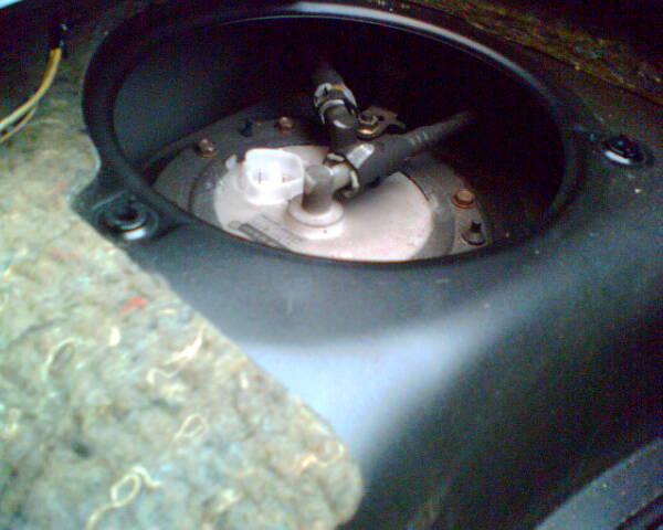
Here's where the pump lives!
Unbolt the 8 screws and you can now carefully pull up the fuel pump assembly.

The fuel level gauge sits at the bottom and this needs "angling" a bit to get it out the hole.
Here's the fuel pump out.
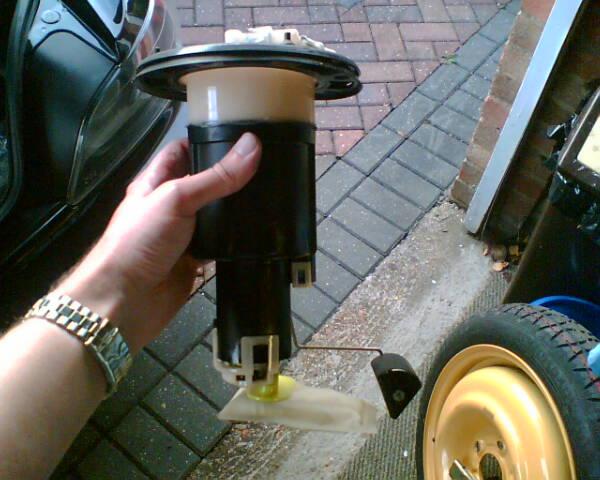
And the old and new pumps side by side.
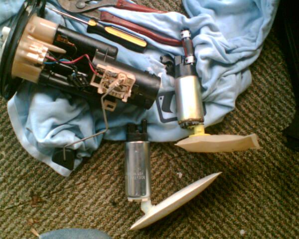
Disconnect the connector plug on the fuel pump and remove the white plastic retainer at the bottom, then pull the fuel pump down and out. Remove the half moon bit of rubber off the filter / pump.
Then remove the little retainer that holds the filter on, and push it down over the new pump / filter to secure the filter in place.
Then attatch the hose from the old one, onto the new one. You will need to shave off about 5mm from the existing hose, because the length of the new pump is greater than the old one - and that would mean it would stop the float hitting the bottom!
Once this is done, replace the plastic clip and half moon bit of rubber, and stick it back in the tank - be careful not to bend the level float!
All in all this took me 3 hours - and the fumes made me rather dizzy
MB
Right, finally got the fuel pump pics uploaded! I put plenty of detail into this as it can be seen as tricky. Pretty straight forward tbh!
First of all, pull out fuse no 12 under in the fuse box the steering wheel. This is the fuel pump fuse. Then try and start the engine twice. This sucks all the fuel out the lines - hopefully! Then open the fuel cap to release any pressure, and replace.
Ok, the fuel pump lives behind the boot panel where the spare wheel lives, so first step is open the boot! Then remove the spare wheel panel.
The pump is to the left, out of shot.
Need to remove the rear tray behind the hood, as it creates access to the top of the fuel pump. This is a bit of a bastard as you have to work kneeling on the seat and reaching between the roll hoops. The black plastic clips you can see have a little round bit in the middle. Push these in and you can then pull out the whole clip. The hardest ones are behind the seat area as you cant see what you're doing! There are 3 white ones which have to be pushed up through from the boot. Dont try and prise them up.
Remove the panel below, through the boot.
Remove 3 screws to uncover the fuel lines and pump lid. Push the clips in on the fuel hoses and pull off the hose, and unplug the connector. The return on the right wont spray you, but the other probably will! Use a rag around it to keep it all contained.
Here's where the pump lives!
Unbolt the 8 screws and you can now carefully pull up the fuel pump assembly.
The fuel level gauge sits at the bottom and this needs "angling" a bit to get it out the hole.
Here's the fuel pump out.
And the old and new pumps side by side.
Disconnect the connector plug on the fuel pump and remove the white plastic retainer at the bottom, then pull the fuel pump down and out. Remove the half moon bit of rubber off the filter / pump.
Then remove the little retainer that holds the filter on, and push it down over the new pump / filter to secure the filter in place.
Then attatch the hose from the old one, onto the new one. You will need to shave off about 5mm from the existing hose, because the length of the new pump is greater than the old one - and that would mean it would stop the float hitting the bottom!
Once this is done, replace the plastic clip and half moon bit of rubber, and stick it back in the tank - be careful not to bend the level float!
All in all this took me 3 hours - and the fumes made me rather dizzy
MB