
2001 Honda S2000 Build Thread


Thread Starter
Registered User
Joined: Mar 2010
Posts: 698
Likes: 0
Completed a-pillar pods
*Self adhering closed cell foam behind the pods + threaded nuts. The foam is there to prevent any unwanted twist, noise, or resonance between the parts. The threaded bolts go into existing pillar mounting holes so the chassis metal was left untouched. Pillars can be take off or tightened fairly easily, one bolt behind each speaker.

*Wiring ran through, one end has modular Anderson power poles and connects to the amplifier wiring, the other quick disconnects for the speakers. Hot glue poured over to ensure air tight seal.

*Air motion transformers mounted up top after pillars are bolted to the a-pillar using machine screws. Aluminum damping sheets added to reduce resonance in the midrange.


*Open cell foam added behind the planar midrange. 1" thickness should absorb the rear wave entirely above 1khz, and a good amount under 1khz. ~1.75" open space left between midrange and foam, 2.75" total depth excedes the minimum recommended by the manufacturer. AMT tweeters come with an OEM rear wave absorption felt piece.

*Finished pods


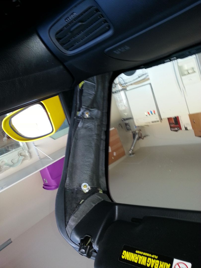
The fiberglass mold accounted for the A/C vents behind the panels. Those are double sticky taped on the pillar behind the speaker and work as intended. Driver pod does not extend past the A/C vent in the dash and therefore maintains enough spacing between pod and steering wheel to operate vehicle. Passenger pod is shallow enough to clear the air bag lid if needed during an accident. Both pods are built to take 0 glass viewing area from the driver's seat ensuring visibility. All connections are quick disconnects and all bolts are machine threaded so that they are easy to service. Replacement speakers are also readily available.
This completes the fabrication portion of the a-pillars. Software based testing and optimization to follow.
*Self adhering closed cell foam behind the pods + threaded nuts. The foam is there to prevent any unwanted twist, noise, or resonance between the parts. The threaded bolts go into existing pillar mounting holes so the chassis metal was left untouched. Pillars can be take off or tightened fairly easily, one bolt behind each speaker.
*Wiring ran through, one end has modular Anderson power poles and connects to the amplifier wiring, the other quick disconnects for the speakers. Hot glue poured over to ensure air tight seal.
*Air motion transformers mounted up top after pillars are bolted to the a-pillar using machine screws. Aluminum damping sheets added to reduce resonance in the midrange.
*Open cell foam added behind the planar midrange. 1" thickness should absorb the rear wave entirely above 1khz, and a good amount under 1khz. ~1.75" open space left between midrange and foam, 2.75" total depth excedes the minimum recommended by the manufacturer. AMT tweeters come with an OEM rear wave absorption felt piece.
*Finished pods
The fiberglass mold accounted for the A/C vents behind the panels. Those are double sticky taped on the pillar behind the speaker and work as intended. Driver pod does not extend past the A/C vent in the dash and therefore maintains enough spacing between pod and steering wheel to operate vehicle. Passenger pod is shallow enough to clear the air bag lid if needed during an accident. Both pods are built to take 0 glass viewing area from the driver's seat ensuring visibility. All connections are quick disconnects and all bolts are machine threaded so that they are easy to service. Replacement speakers are also readily available.
This completes the fabrication portion of the a-pillars. Software based testing and optimization to follow.
Thread Starter
Registered User
Joined: Mar 2010
Posts: 698
Likes: 0
Kickpanel build Part I of II
I had two choices for bass producing techonology, the Peerless 10" MAC XLS, which reverses the motor and the Tympany LAT250 which arranges smaller cones in a mechanical push-pull connected by carbon fiber rods. Needless to say the LAT250s take up more room to produce the same amount of output and need a lot more airspace than I can provide them. In return they minimize vibration. So I went with the Peerless 10" MAC XLS. I also like the simplicity of installing a single 10" speaker instead of 40 2.5" cones when I'm short on time. Aka I didn't really have time, room, or box space to make them work on this car, so I'm saving the LATs for the next car. They are a piece of speaker design history!
The Peerless 10" XLS MAC, essentially a reverse motor 10" woofer perfectly executed:

Front:

Back:

The Peerless shallow mount 10" is my favorite of all shallow 10" subs and here is why. Klippel tests show 8+mm of true linear excursion when using suspension, inductance, and motor limits. The curves are perfectly symmetrical around the rest position, aka perfectly optimized. QTS is very low and FS is very low so this driver is supremely sensitive at low frequencies where I need it to work. That means in small boxes it will have very extended response, it will need very little power, and it will have a very low resonance. The motor itself is a masterpiece, low inductance, beefy coil, and it's clad entirely in aluminum to heatsink it for high power applications. Unlike other 10" shallow designs this one is resonance free all the way to 700hz which makes it a dual purpose woofer and subwoofer, not just an air pump.
Needless to say I love how Peerless creates revolutionary technology for the masses. It may lose 1db of output to something like an Alpine Type R but this is fine art compared to the Alpine, so much so that I see no reason not to use it as a low midrange. It's also the shallowest design by far on the market and I'll show why.
Next up, fiberglassing the bottom of the enclosure. I chose to fiberglass it on the car to use every nook and cranny available in the S2000 to maximize box size:

As you can see, the driver's side looks helpless. The kick panel holds the dead pedal and computer wiring. Even with all those removed not much can be achieved. So I looked up and noticed a huge air vent (removed in the picture). I took it out, rerouted my alarm wires and my audio wires and made just enough room to flush mount the 10" there. The air vent still works, the pipe opens in the upper left corner now instead of over the legs.
The passenger side is even worse:

The a/c compressor is huge and already takes up loads of leg room. For the purpose of symmetry I decided to mount it downfiring just like the driver woofer, despite this one taking up some passenger legroom. In effect I can stay in that seat and extend my legs all the way out under the speaker but it is a bit intrusive. I should have fiberglassed it as a standard kickpanel instead, oh well, too late now.
Car getting prepped:


That pointy part of the a/c compressor is more than a pain.
Hoping to retain OEM looking kick panels I fiberglassed the OEM plastic kickpanel to reproduce it out of fiberglass.


I had two choices for bass producing techonology, the Peerless 10" MAC XLS, which reverses the motor and the Tympany LAT250 which arranges smaller cones in a mechanical push-pull connected by carbon fiber rods. Needless to say the LAT250s take up more room to produce the same amount of output and need a lot more airspace than I can provide them. In return they minimize vibration. So I went with the Peerless 10" MAC XLS. I also like the simplicity of installing a single 10" speaker instead of 40 2.5" cones when I'm short on time. Aka I didn't really have time, room, or box space to make them work on this car, so I'm saving the LATs for the next car. They are a piece of speaker design history!
The Peerless 10" XLS MAC, essentially a reverse motor 10" woofer perfectly executed:
Front:
Back:
The Peerless shallow mount 10" is my favorite of all shallow 10" subs and here is why. Klippel tests show 8+mm of true linear excursion when using suspension, inductance, and motor limits. The curves are perfectly symmetrical around the rest position, aka perfectly optimized. QTS is very low and FS is very low so this driver is supremely sensitive at low frequencies where I need it to work. That means in small boxes it will have very extended response, it will need very little power, and it will have a very low resonance. The motor itself is a masterpiece, low inductance, beefy coil, and it's clad entirely in aluminum to heatsink it for high power applications. Unlike other 10" shallow designs this one is resonance free all the way to 700hz which makes it a dual purpose woofer and subwoofer, not just an air pump.
Needless to say I love how Peerless creates revolutionary technology for the masses. It may lose 1db of output to something like an Alpine Type R but this is fine art compared to the Alpine, so much so that I see no reason not to use it as a low midrange. It's also the shallowest design by far on the market and I'll show why.
Next up, fiberglassing the bottom of the enclosure. I chose to fiberglass it on the car to use every nook and cranny available in the S2000 to maximize box size:
As you can see, the driver's side looks helpless. The kick panel holds the dead pedal and computer wiring. Even with all those removed not much can be achieved. So I looked up and noticed a huge air vent (removed in the picture). I took it out, rerouted my alarm wires and my audio wires and made just enough room to flush mount the 10" there. The air vent still works, the pipe opens in the upper left corner now instead of over the legs.
The passenger side is even worse:
The a/c compressor is huge and already takes up loads of leg room. For the purpose of symmetry I decided to mount it downfiring just like the driver woofer, despite this one taking up some passenger legroom. In effect I can stay in that seat and extend my legs all the way out under the speaker but it is a bit intrusive. I should have fiberglassed it as a standard kickpanel instead, oh well, too late now.
Car getting prepped:
That pointy part of the a/c compressor is more than a pain.
Hoping to retain OEM looking kick panels I fiberglassed the OEM plastic kickpanel to reproduce it out of fiberglass.


Joined: Sep 2004
Posts: 1,574
Likes: 62
From: NJ USA
a bunch of years ago someone put a JL 6W0 into that driver's footwell location - I've always thought it was clever,
though yours takes it to a whole new level!
JL 6W0 install
though yours takes it to a whole new level!
JL 6W0 install
Thread Starter
Registered User
Joined: Mar 2010
Posts: 698
Likes: 0
Kickpanel build Part II of II
I intended to make a kickpanel that is really a big speaker box using the airspace in the kickpanel and under the dash. In reality, there was no air space in the kickpanels without losing the deadpedal. I decided to keep the S2000 as useful as without the audio so the kickpanel portion is really only a face, not an enclosure. It hides the wires and bolts itself to the car's frame. That way the speaker fires from under the dash but does not vibrate the dashboard. It only touches the car in the kick area. This way I got all the vibration free operation I could get, did not intrude on any driver leg room, but have to do with a smaller speaker box.
I added one layer of fiberglass in the car under the dash to get the shape and 6 layers+ on the kick parts. Pulled them off the molds and layed them in the sun to cure. The entire kick build process took me 20 labor hours over 2 days so it was fast and the sun helped a lot. 110 degree weather!

Next up I added 5 more layers on the underdash piece. Let it cure, then trimmed it. As it was drying I noticed it was curling and the angle between kick and dashboard was getting lower. I added some weights on the back piece to force it back as it was drying.

This is the step when the two fiberglass pieces come together with a wood baffle and things start making sense. I used wooden dowels and hot glue to get the three parts to come together as tight as possible. The speaker has 1/4" extra depth at most. Even the speaker basket is less than 1/4" away from the fiberglass bits in places. On the passenger side, the protrusion from the A/C compressor fits in between the spokes of the speaker basket. Can't do that with any other 10" woofer!

Passenger kick in the forefront. You can see the protrusion on the lower left. The speaker fits around it.

Fitting the enclosure in the car was very difficult. There are many angles that can be fiberglassed, but it doesn't mean that you can remove the mold. After a lot of trimming this is what could fit back in the car as one unit:


Added the remaining fiberglass to seal the pods. The wooden baffle was soaked in resin and painted to add waterproofness over time.


These are final pics before I had them wrapped in leather. Trimmed and surfaced, some body filler was added later to smoothen the shape but didn't have time to shoot a pic, they were due at the upholstery shop:

I intended to make a kickpanel that is really a big speaker box using the airspace in the kickpanel and under the dash. In reality, there was no air space in the kickpanels without losing the deadpedal. I decided to keep the S2000 as useful as without the audio so the kickpanel portion is really only a face, not an enclosure. It hides the wires and bolts itself to the car's frame. That way the speaker fires from under the dash but does not vibrate the dashboard. It only touches the car in the kick area. This way I got all the vibration free operation I could get, did not intrude on any driver leg room, but have to do with a smaller speaker box.
I added one layer of fiberglass in the car under the dash to get the shape and 6 layers+ on the kick parts. Pulled them off the molds and layed them in the sun to cure. The entire kick build process took me 20 labor hours over 2 days so it was fast and the sun helped a lot. 110 degree weather!
Next up I added 5 more layers on the underdash piece. Let it cure, then trimmed it. As it was drying I noticed it was curling and the angle between kick and dashboard was getting lower. I added some weights on the back piece to force it back as it was drying.
This is the step when the two fiberglass pieces come together with a wood baffle and things start making sense. I used wooden dowels and hot glue to get the three parts to come together as tight as possible. The speaker has 1/4" extra depth at most. Even the speaker basket is less than 1/4" away from the fiberglass bits in places. On the passenger side, the protrusion from the A/C compressor fits in between the spokes of the speaker basket. Can't do that with any other 10" woofer!
Passenger kick in the forefront. You can see the protrusion on the lower left. The speaker fits around it.
Fitting the enclosure in the car was very difficult. There are many angles that can be fiberglassed, but it doesn't mean that you can remove the mold. After a lot of trimming this is what could fit back in the car as one unit:
Added the remaining fiberglass to seal the pods. The wooden baffle was soaked in resin and painted to add waterproofness over time.
These are final pics before I had them wrapped in leather. Trimmed and surfaced, some body filler was added later to smoothen the shape but didn't have time to shoot a pic, they were due at the upholstery shop:
Thread Starter
Registered User
Joined: Mar 2010
Posts: 698
Likes: 0
Finished Product Kicks/dash pods
Leather wrapping passenger side:

Driver's side:

Kicks were bolted to the chassis using machine screws again. Threaded nuts went into the original holes made for plastic kicks.
Driver's side, can't normally see it:

Both bolts can be seen in this picture. Deadpedal use unaffected. Hood release latch unaffected, and a bulge is made into the kick to prevent accidental opening like on the stock one.


Passenger side. I don't really like the way it takes up space or the way it looks there but it works and doesn't bother me.


Maybe in the future I will make another passenger kick mounted in a more traditional fashion aimed at the center tunnel. I think that would be nicer to look at and take up less room. No easy way to get a 10" on the passenger side.
Leather wrapping passenger side:
Driver's side:
Kicks were bolted to the chassis using machine screws again. Threaded nuts went into the original holes made for plastic kicks.
Driver's side, can't normally see it:
Both bolts can be seen in this picture. Deadpedal use unaffected. Hood release latch unaffected, and a bulge is made into the kick to prevent accidental opening like on the stock one.
Passenger side. I don't really like the way it takes up space or the way it looks there but it works and doesn't bother me.
Maybe in the future I will make another passenger kick mounted in a more traditional fashion aimed at the center tunnel. I think that would be nicer to look at and take up less room. No easy way to get a 10" on the passenger side.
Thread Starter
Registered User
Joined: Mar 2010
Posts: 698
Likes: 0
Subwoofer build
From earlier, this is the fiberglass cage I built to separate the trunk and inside airspaces. It provides a simple solution to mounting a 37" by 13" subwoofer baffle. The 37" width is dictated by the space between the trunk support arms.
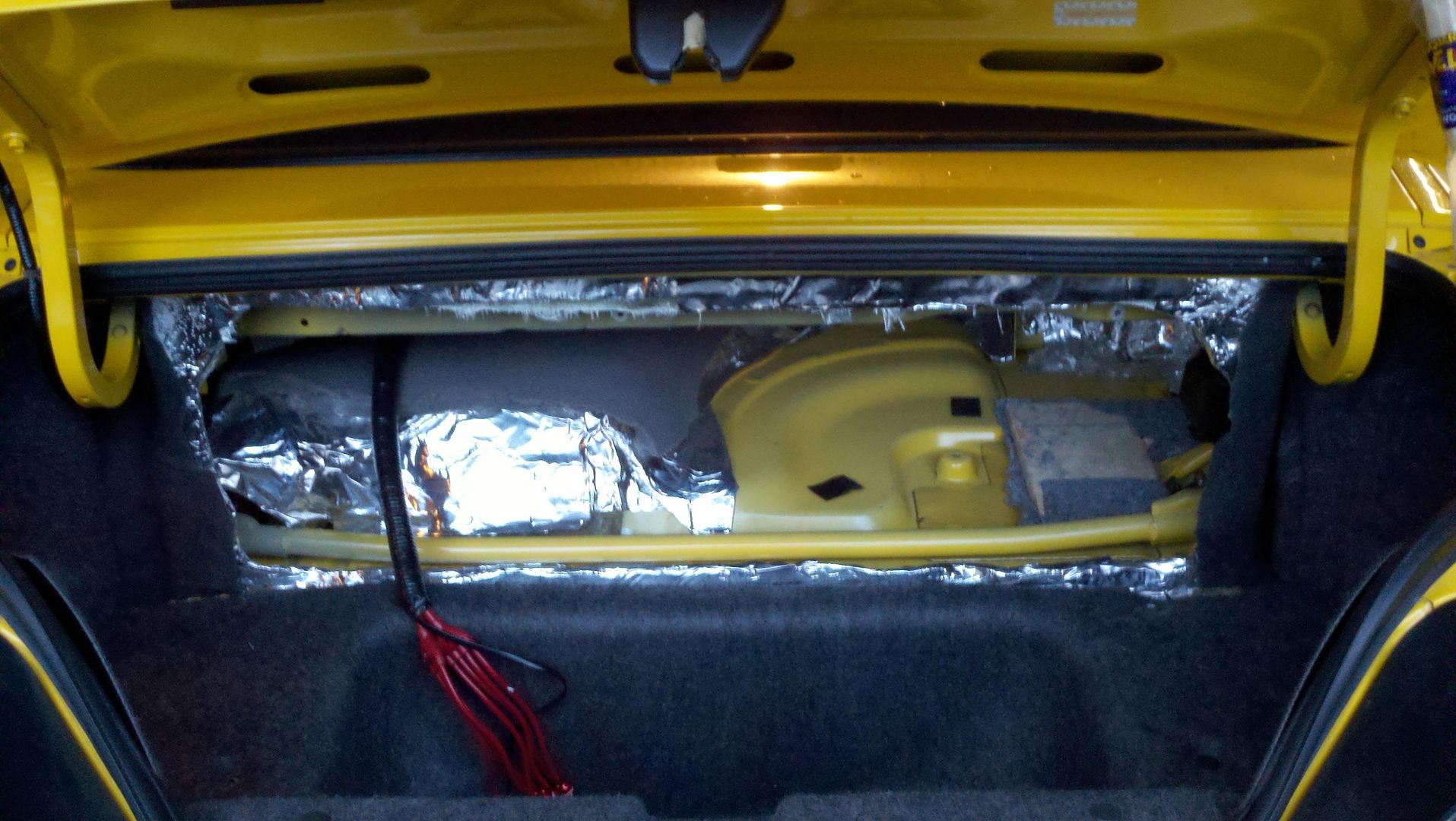
After trying out countless 12"s and 15"s, I have come to the conclusion that the none perform even close to the Tympani LAT. So I went back to them. Two LAT700s house twelve 7" subs in a vibration canceling push-pull orientation. As mentioned eariler, the trouble with two LAT700s is that the width is 38.5" so it doesn't clear my trunk supports.
This is an earlier picture where I removed the center caps and used silicone adhesive to seal the baffle in the middle in the absence of endcaps:

As a permanent solution I had the two endcaps soldered together. This was a tough job because the endcaps are aluminum. Here is what they look like now, width is 36.5" which just clears my trunk support arms:

Made a new baffle and wrapped it in carpet:

Wired all motors, 4 in all, in parallel for a final 1 ohm load. 12 gauge wiring, fan over thread connectors, and Anderson powerpoles quick disconnects to remove the baffle easily for track days:

In car pics:


From earlier, this is the fiberglass cage I built to separate the trunk and inside airspaces. It provides a simple solution to mounting a 37" by 13" subwoofer baffle. The 37" width is dictated by the space between the trunk support arms.
After trying out countless 12"s and 15"s, I have come to the conclusion that the none perform even close to the Tympani LAT. So I went back to them. Two LAT700s house twelve 7" subs in a vibration canceling push-pull orientation. As mentioned eariler, the trouble with two LAT700s is that the width is 38.5" so it doesn't clear my trunk supports.
This is an earlier picture where I removed the center caps and used silicone adhesive to seal the baffle in the middle in the absence of endcaps:
As a permanent solution I had the two endcaps soldered together. This was a tough job because the endcaps are aluminum. Here is what they look like now, width is 36.5" which just clears my trunk support arms:
Made a new baffle and wrapped it in carpet:
Wired all motors, 4 in all, in parallel for a final 1 ohm load. 12 gauge wiring, fan over thread connectors, and Anderson powerpoles quick disconnects to remove the baffle easily for track days:
In car pics:
Thread Starter
Registered User
Joined: Mar 2010
Posts: 698
Likes: 0
Each motor is rated at 500w, there are two per each array, with two arrays like mine total output is 2000w rms. My amp is an ARC Audio KS pushing 1200w.

