
Frankenstook cold side supercharger build

Thread Starter


Joined: Sep 2002
Posts: 4,784
Likes: 2
From: Greer, SC
Way back in 2007, I picked up a totaled s2000 from a front-end collision and started building it into a dual purpose track/autocross car that's affectionately been named 'Frankenstook'. For the last several years, it's been a dedicated autocross car, and become quite competitive, finishing as high as 3rd at the Solo National Championships in F Prepared. Here's a pic of the car as it ran at the 2015 Nationals (4th place finish).

Last fall, I decided I wanted more power, and that I'd change classes to one that allows forced induction. I knew that for autocross, I wanted instant torque, with a broad, flat curve, and I didn't care much about peak numbers. In short, I wanted a positive displacement supercharger. With the SOT kit no longer available and extremely rare, I knew it was unlikely that I'd find one used. So, I decided to roll my own. This thread will document how I did it. I will say, however, that reproducing this on a street car will present more challenges that I haven't addressed.
Initially, I planned to modify a stock manifold, but pretty quickly I ran across mercracing.net. The owner, Jose, sells a low-volume supercharger kit for K-series hondas that is based around a modular cast aluminum manifold:
As the K-series and the F20/F22's share the same intake port shape and spacing, I felt like this might be a good starting point.
I was also incredibly lucky that Jose is both an awesome guy, and recently moved within a 2 hour drive of me. After exchanging emails, he drove down to my house and brought a manifold to see if it would even remotely be workable. As it turns out, the manifold itself fits remarkably well in the space provided.

Several problems presented themselves, though:
1) I needed an adapter plate to convert the k-manifold to the f-series bolt pattern.
2) The modular output portion of the manifold was designed for FWD applications, and as such, it both faced the firewall, and interfered with the starter
3) The intake side of the blower would end up very close to the firewall. Throttle body, intake piping and air filter are all going to be a challenge.
4) Charge piping would need to occupy the same physical space as the lower radiator hose and the alternator
5) (discovered later) the stock brake booster clears the manifold with no problem, but interferes with the body of the blower
6) I wanted to run a single serpantine belt, and the stock crank pulley is pretty small. I needed a solution for a larger diameter pulley.
I decided that I could probably overcome all of those, and placed an order with Jose for a manifold, and a magunson MP1320 supercharger in late 2015. His manifolds are produced in batches by a foundry, and I caught him between orders with no inventory, so I had to wait for the next batch. I finally picked mine up on May 1, along with the blower, and the real work began!
I should point out that the first few posts here may not be in exactly chronological order , as I wasn't all that organized when actually doing the work. I figured that sorting the work by topic would be easier to follow, though.
Last fall, I decided I wanted more power, and that I'd change classes to one that allows forced induction. I knew that for autocross, I wanted instant torque, with a broad, flat curve, and I didn't care much about peak numbers. In short, I wanted a positive displacement supercharger. With the SOT kit no longer available and extremely rare, I knew it was unlikely that I'd find one used. So, I decided to roll my own. This thread will document how I did it. I will say, however, that reproducing this on a street car will present more challenges that I haven't addressed.
Initially, I planned to modify a stock manifold, but pretty quickly I ran across mercracing.net. The owner, Jose, sells a low-volume supercharger kit for K-series hondas that is based around a modular cast aluminum manifold:
As the K-series and the F20/F22's share the same intake port shape and spacing, I felt like this might be a good starting point.
I was also incredibly lucky that Jose is both an awesome guy, and recently moved within a 2 hour drive of me. After exchanging emails, he drove down to my house and brought a manifold to see if it would even remotely be workable. As it turns out, the manifold itself fits remarkably well in the space provided.
Several problems presented themselves, though:
1) I needed an adapter plate to convert the k-manifold to the f-series bolt pattern.
2) The modular output portion of the manifold was designed for FWD applications, and as such, it both faced the firewall, and interfered with the starter
3) The intake side of the blower would end up very close to the firewall. Throttle body, intake piping and air filter are all going to be a challenge.
4) Charge piping would need to occupy the same physical space as the lower radiator hose and the alternator
5) (discovered later) the stock brake booster clears the manifold with no problem, but interferes with the body of the blower
6) I wanted to run a single serpantine belt, and the stock crank pulley is pretty small. I needed a solution for a larger diameter pulley.
I decided that I could probably overcome all of those, and placed an order with Jose for a manifold, and a magunson MP1320 supercharger in late 2015. His manifolds are produced in batches by a foundry, and I caught him between orders with no inventory, so I had to wait for the next batch. I finally picked mine up on May 1, along with the blower, and the real work began!
I should point out that the first few posts here may not be in exactly chronological order , as I wasn't all that organized when actually doing the work. I figured that sorting the work by topic would be easier to follow, though.
Thread Starter
Joined: Sep 2002
Posts: 4,784
Likes: 2
From: Greer, SC
So, on to problem number #1, or "How the hell am I going to bolt this thing to the s2000 head?"
While dropping a K-motor into the car certainly would be a viable option, I decided to figure out how to adapt the manifold instead. Thankfully, in pretty short order I found an F20c/F22c to K series adapter plate being produced by a company out of New Jersey, www.pro-jay.com.

I see that they no longer list the adapter on their website, so I'm not sure if they will still make them or not, but it's a good piece. It's a half inch thick, includes all the mounting bolts, and really fits well. At $225, it wasn't outrageously priced, either. Here's the adapter as I received it, mated to an s2000 head:

I was a little worried that the adapter reduced the water port on the back of the head down to a 3/4 NPT fitting, but there's not much I can do about it without having another adapter made to experiment on. I decided to ignore this for now and deal with it later, so I purchased a 3/4 NPT to 1.25 hose barb fitting and installed it. I also installed a 3/8 NPT plug in the port above the water outlet, which connects to the exhaust -- it's the passage through which the stock air pump flows, and that's long gone on my car!
I did, however, want to retain the water port on the front of the head. As my car has no heater core, nor any of the original coolant plumbing, I need that port to properly bleed the coolant system. I used an s2000 intake manifold gasket to mark the location, then drilled two intersecting holes in the adapter, one from the back, centered on the mark, and one from the side, facing the front of the car. I then enlarged that second hole and tapped it for 1/16th NPT and installed a barb fitting:

I capped the fitting with a rubber cap and a ziptie to hold it in place.
I also wanted to port-match the adapter to the gaskets:
K gasket taped in place to mark material for removal:

... and after making a bunch of aluminum shavings with a micro mill:

And here we have it... bolted to my spare motor!

The top-front bolt hole on the k-manifold does need to be re-drilled to match up with the s2000, but that was the only modification necessary to the manifold flange. I also eventually removed the stud and replaced it with a longer bolt.
So, that's the adapter solved!
While dropping a K-motor into the car certainly would be a viable option, I decided to figure out how to adapt the manifold instead. Thankfully, in pretty short order I found an F20c/F22c to K series adapter plate being produced by a company out of New Jersey, www.pro-jay.com.
I see that they no longer list the adapter on their website, so I'm not sure if they will still make them or not, but it's a good piece. It's a half inch thick, includes all the mounting bolts, and really fits well. At $225, it wasn't outrageously priced, either. Here's the adapter as I received it, mated to an s2000 head:
I was a little worried that the adapter reduced the water port on the back of the head down to a 3/4 NPT fitting, but there's not much I can do about it without having another adapter made to experiment on. I decided to ignore this for now and deal with it later, so I purchased a 3/4 NPT to 1.25 hose barb fitting and installed it. I also installed a 3/8 NPT plug in the port above the water outlet, which connects to the exhaust -- it's the passage through which the stock air pump flows, and that's long gone on my car!
I did, however, want to retain the water port on the front of the head. As my car has no heater core, nor any of the original coolant plumbing, I need that port to properly bleed the coolant system. I used an s2000 intake manifold gasket to mark the location, then drilled two intersecting holes in the adapter, one from the back, centered on the mark, and one from the side, facing the front of the car. I then enlarged that second hole and tapped it for 1/16th NPT and installed a barb fitting:
I capped the fitting with a rubber cap and a ziptie to hold it in place.
I also wanted to port-match the adapter to the gaskets:
K gasket taped in place to mark material for removal:
... and after making a bunch of aluminum shavings with a micro mill:
And here we have it... bolted to my spare motor!
The top-front bolt hole on the k-manifold does need to be re-drilled to match up with the s2000, but that was the only modification necessary to the manifold flange. I also eventually removed the stud and replaced it with a longer bolt.
So, that's the adapter solved!
Thread Starter
Joined: Sep 2002
Posts: 4,784
Likes: 2
From: Greer, SC
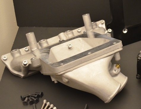
So... on to problem #2: making the bottom portion of the manifold fit.
Since the manifold was designed for front wheel drive cars, the 2.5 inch output/input ports now face the firewall. I wanted to run an air-to-air intercooler, so I needed to at least turn those around to face the front of the car. Also, the starter interfered with the manifold here:

I'd already started trying to modify the manifold for clearance at that point. Eventually, I decided to cut the whole thing apart, parallel with the mounting flange and build all new output ports.
mockup:


I ended up using the same basic configuration as above, with 1/4 inch aluminum plate for the horizontal surface, but instead of using the thin wall tubing, I was able to salvage the original cast ports. They were thick and stood up to my ham-fisted welding way better.
Somewhere around this point, I realized that there was no way I'd be able to keep the stock thermostat housing, as the charge pipe for the feed to the manifold would need to be in exactly the same space. I'd already been planning to run an electric water pump anyway, so removing the whole water pump housing wasn't a big concern.
I only managed to get pics of the finished product from the back side, after I spent forever sanding it back to flat due to warpage from that aforementioned welding:

Since the manifold was designed for front wheel drive cars, the 2.5 inch output/input ports now face the firewall. I wanted to run an air-to-air intercooler, so I needed to at least turn those around to face the front of the car. Also, the starter interfered with the manifold here:
I'd already started trying to modify the manifold for clearance at that point. Eventually, I decided to cut the whole thing apart, parallel with the mounting flange and build all new output ports.
mockup:
I ended up using the same basic configuration as above, with 1/4 inch aluminum plate for the horizontal surface, but instead of using the thin wall tubing, I was able to salvage the original cast ports. They were thick and stood up to my ham-fisted welding way better.
Somewhere around this point, I realized that there was no way I'd be able to keep the stock thermostat housing, as the charge pipe for the feed to the manifold would need to be in exactly the same space. I'd already been planning to run an electric water pump anyway, so removing the whole water pump housing wasn't a big concern.
I only managed to get pics of the finished product from the back side, after I spent forever sanding it back to flat due to warpage from that aforementioned welding:
Thread Starter
Joined: Sep 2002
Posts: 4,784
Likes: 2
From: Greer, SC
Problem #3: The blower is _really_ close to the firewall.

No, really... It's so close to the firewall, that there's no way to attach a throttle body.
This is the point where, if you own a garage queen and are opposed to brute-force solutions, I suggest you quit reading. Just walk away and pretend you never saw this.
You've been warned.
Ok, so I needed to fit, at a minimum, a throttle body and some sort of intake elbow here:

When building a Prepared class racecar, and faced with making parts fit where there's not enough space, the tools of choice are: a BFH, grinder, or sawzall.
I started with the BFH:

... and more persuasion with the BFH:

While I made a good bit of space, there still wasn't enough, so out came the grinder and cutoff wheel:

There we go... now we're getting somewhere!


All that cutting let me mock up an intake elbow and my k-tuned 90mm throttle body:

1/4 inch plate of aluminum cut and matched to the blower as a starting point for the intake elbow:

and the final intake elbow welded up. This started as a cast aluminum LT1 intake elbow, which I cut down and welded to an aluminum throttle body flange and the plate in the previous pic:

Due to the inward bulge in the firewall, I had to modify the throttle pedal assembly to move the cable pickup about an inch to the left.

Now to close up those holes and make the firewall a functional firewall again!


Yes, it's ugly. I'm a terrible welder and completely impatient. Remember... you were warned earlier!
On to problem #4: charge pipes and thermostat housing can't occupy the same space.
Thankfully, this solution didn't involve the BFH or the sawzall. With the stock water pump housing unbolted and removed, there was plenty of space, and since I wanted to run an electric water pump anyway, I just decided to leave the whole housing off and make an adapter plate:

An accord coolant neck completed that task. I eventually replaced the stacked adapter and fan switch with an M18 threaded fan switch that screws directly into the accord housing.

No, really... It's so close to the firewall, that there's no way to attach a throttle body.
This is the point where, if you own a garage queen and are opposed to brute-force solutions, I suggest you quit reading. Just walk away and pretend you never saw this.
You've been warned.
Ok, so I needed to fit, at a minimum, a throttle body and some sort of intake elbow here:
When building a Prepared class racecar, and faced with making parts fit where there's not enough space, the tools of choice are: a BFH, grinder, or sawzall.
I started with the BFH:
... and more persuasion with the BFH:
While I made a good bit of space, there still wasn't enough, so out came the grinder and cutoff wheel:
There we go... now we're getting somewhere!
All that cutting let me mock up an intake elbow and my k-tuned 90mm throttle body:
1/4 inch plate of aluminum cut and matched to the blower as a starting point for the intake elbow:
and the final intake elbow welded up. This started as a cast aluminum LT1 intake elbow, which I cut down and welded to an aluminum throttle body flange and the plate in the previous pic:
Due to the inward bulge in the firewall, I had to modify the throttle pedal assembly to move the cable pickup about an inch to the left.
Now to close up those holes and make the firewall a functional firewall again!
Yes, it's ugly. I'm a terrible welder and completely impatient. Remember... you were warned earlier!
On to problem #4: charge pipes and thermostat housing can't occupy the same space.
Thankfully, this solution didn't involve the BFH or the sawzall. With the stock water pump housing unbolted and removed, there was plenty of space, and since I wanted to run an electric water pump anyway, I just decided to leave the whole housing off and make an adapter plate:
An accord coolant neck completed that task. I eventually replaced the stacked adapter and fan switch with an M18 threaded fan switch that screws directly into the accord housing.
Thread Starter
Joined: Sep 2002
Posts: 4,784
Likes: 2
From: Greer, SC
Problem #5: Brake booster and blower can't occupy the same space.
For those with keen eyes, you probably saw in the early pics that I was running a dual master cylinder setup with no brake booster. I wanted to switch back to boosted brakes, as I never quite got the dual MC setup dialed in and really never felt all that comfortable with it. I also figured that while it might be passable at the power level I was running NA, I might want to err on the side of caution and have power brakes with the new setup.
The stock brake booster is around 11 inches in diameter, and something like 3.5 inches deep. These are ballpark numbers from memory. I think it also weighed around 6 pounds. Regardless, it couldn't occupy the same space as the blower, so I had to find something smaller. After trying out a booster from summit racing and not liking how it fit, I found several forum posts on different sites touting the awesomeness that is the booster from... the mighty GEO METRO!!! Yep. the little 3-cylinder econo-box. Turns out, the brake booster is made by nissin. It's only about 7 inches in diameter and weighs 3 pounds. It's apparently a commonly used part by hot rod guys. It also happens to have exactly the same bolt pattern as our stock booster. So... after a trip to the local junkyard, I had a 'fresh' booser off of a 1992 metro!


Though I don't have specific pictures of it, the stock brake master cylinder bolts right up to the metro booster, and I was able to reuse the stock hardlines by just massaging a few of the bends to gain a little length. As for function.... it works pretty well, but does not provide the same amount of boost that the stock booster does. I would like to get a stock booster back in there eventually.
On to problem #6: The crank pulley.
The stock s2000 crank pulley is about 5.5 inches in diameter, and I wanted to run a single serpentine belt. With a 3 inch blower pulley, that would only give me around 15700 rpm on the blower at an engine rpm of 8600. After buying and test fitting several options, I went with a K24 crank pulley off of the TSX. It's 6.125 inches in diameter, and gives me 17550 rpm on the blower at redline with the 3 inch blower pulley. Of course, it's also a 7-rib pulley instead of our stock 6-rib. So, I'd need to swap over to 7-rib pulleys for the rest of the system. While the K24 crank pulley fits our crank snout with no problems, it doesn't have the big recess cast into the back to clear the debris shield that is part of the timing cover.
So, this thing needed to go:

Thing, meet Mr. Millingmachine:

And now, we have a timing cover with a much reduced debris shield (and a new oil seal for good measure):

Installation of the modified timing cover, of course, required dropping the oil pan, and was a complete pain the ass.

I did also end up grinding down the cast triangle at the 11 o'clock position on the timing cover. It cleared the pulley, but not by much, and I wanted a bit of room for error. Additionally, for alignment purposes, I installed a 0.020 inch shim between the crank snout and the crank pulley. This allowed me to use the same pulley on the blower that Mercracing supplies for the K-series kits. Since I was going to make my own alternator bracket anyway, spacing the crank pulley out to match the blower was the quickest means to an end.
Here's the K24 crank pulley installed:

I have a larger 6.5 inch crank pulley out of a CRV ordered, and a 2.8 inch blower pulley as well. Those two should net me right at 20k rpm on the blower. I'll give those a go this fall after I redo the fuel system and switch to E85.
So, that's it for all the roadblocks that I had to solve. Now onto more mundane tasks:
I ordered an alternator for a 1.7L 2005 Civic, which conveniently had a 7-rib pulley and the exact same electrical connectors as the s2000 alternator. It's also a couple of pounds lighter. Then I made some brackets out of angle aluminum to install it where the AC compressor originally lived. I slotted the brackets to allow for aligning the pulley:

I added an idler pulley to the upper alternator bracket to provide better belt wrap around the crank pulley:

That done, I mocked up the belt routing. I didn't get a great pic of this, but I added another idler pulley beside the tensioner, using the threaded hole where the stock alternator's upper mounting tab is bolted. I reused the stock s2000 belt tensioner, but swapped out the pulley with a 7-rib aluminum one. I had to shim both pulleys to align with the supercharger and crank.

I'd already been running a half-width Mishimoto radiator, mounted on the passenger side of the radiator support, so after some searching, I found that an FD RX7 intercooler fit the remaining space quite nicely, if turned on it's side:

I also found that the hose barb off of my original thermostat housing made a great mounting barb for the intercooler, so I welded it on. With a piece of radiator hose slipped on, it fits snugly into the stock lower radiator mount on the drivers side.

Then I added an upper mount made out of aluminum z-channel that bolts to the stock upper radiator support.

Charge pipe mockup and a decent shot of the intercooler mounted:

Fuel lines, FPR, and coolant lines all done:

Nearly everything in place (yet to mount the brake master or the throttle body)

For those with keen eyes, you probably saw in the early pics that I was running a dual master cylinder setup with no brake booster. I wanted to switch back to boosted brakes, as I never quite got the dual MC setup dialed in and really never felt all that comfortable with it. I also figured that while it might be passable at the power level I was running NA, I might want to err on the side of caution and have power brakes with the new setup.
The stock brake booster is around 11 inches in diameter, and something like 3.5 inches deep. These are ballpark numbers from memory. I think it also weighed around 6 pounds. Regardless, it couldn't occupy the same space as the blower, so I had to find something smaller. After trying out a booster from summit racing and not liking how it fit, I found several forum posts on different sites touting the awesomeness that is the booster from... the mighty GEO METRO!!! Yep. the little 3-cylinder econo-box. Turns out, the brake booster is made by nissin. It's only about 7 inches in diameter and weighs 3 pounds. It's apparently a commonly used part by hot rod guys. It also happens to have exactly the same bolt pattern as our stock booster. So... after a trip to the local junkyard, I had a 'fresh' booser off of a 1992 metro!
Though I don't have specific pictures of it, the stock brake master cylinder bolts right up to the metro booster, and I was able to reuse the stock hardlines by just massaging a few of the bends to gain a little length. As for function.... it works pretty well, but does not provide the same amount of boost that the stock booster does. I would like to get a stock booster back in there eventually.
On to problem #6: The crank pulley.
The stock s2000 crank pulley is about 5.5 inches in diameter, and I wanted to run a single serpentine belt. With a 3 inch blower pulley, that would only give me around 15700 rpm on the blower at an engine rpm of 8600. After buying and test fitting several options, I went with a K24 crank pulley off of the TSX. It's 6.125 inches in diameter, and gives me 17550 rpm on the blower at redline with the 3 inch blower pulley. Of course, it's also a 7-rib pulley instead of our stock 6-rib. So, I'd need to swap over to 7-rib pulleys for the rest of the system. While the K24 crank pulley fits our crank snout with no problems, it doesn't have the big recess cast into the back to clear the debris shield that is part of the timing cover.
So, this thing needed to go:
Thing, meet Mr. Millingmachine:
And now, we have a timing cover with a much reduced debris shield (and a new oil seal for good measure):
Installation of the modified timing cover, of course, required dropping the oil pan, and was a complete pain the ass.
I did also end up grinding down the cast triangle at the 11 o'clock position on the timing cover. It cleared the pulley, but not by much, and I wanted a bit of room for error. Additionally, for alignment purposes, I installed a 0.020 inch shim between the crank snout and the crank pulley. This allowed me to use the same pulley on the blower that Mercracing supplies for the K-series kits. Since I was going to make my own alternator bracket anyway, spacing the crank pulley out to match the blower was the quickest means to an end.
Here's the K24 crank pulley installed:
I have a larger 6.5 inch crank pulley out of a CRV ordered, and a 2.8 inch blower pulley as well. Those two should net me right at 20k rpm on the blower. I'll give those a go this fall after I redo the fuel system and switch to E85.
So, that's it for all the roadblocks that I had to solve. Now onto more mundane tasks:
I ordered an alternator for a 1.7L 2005 Civic, which conveniently had a 7-rib pulley and the exact same electrical connectors as the s2000 alternator. It's also a couple of pounds lighter. Then I made some brackets out of angle aluminum to install it where the AC compressor originally lived. I slotted the brackets to allow for aligning the pulley:
I added an idler pulley to the upper alternator bracket to provide better belt wrap around the crank pulley:
That done, I mocked up the belt routing. I didn't get a great pic of this, but I added another idler pulley beside the tensioner, using the threaded hole where the stock alternator's upper mounting tab is bolted. I reused the stock s2000 belt tensioner, but swapped out the pulley with a 7-rib aluminum one. I had to shim both pulleys to align with the supercharger and crank.
I'd already been running a half-width Mishimoto radiator, mounted on the passenger side of the radiator support, so after some searching, I found that an FD RX7 intercooler fit the remaining space quite nicely, if turned on it's side:
I also found that the hose barb off of my original thermostat housing made a great mounting barb for the intercooler, so I welded it on. With a piece of radiator hose slipped on, it fits snugly into the stock lower radiator mount on the drivers side.
Then I added an upper mount made out of aluminum z-channel that bolts to the stock upper radiator support.
Charge pipe mockup and a decent shot of the intercooler mounted:
Fuel lines, FPR, and coolant lines all done:
Nearly everything in place (yet to mount the brake master or the throttle body)
Last edited by SC_Highlander; Jul 10, 2018 at 05:14 AM.
Thread Starter
Joined: Sep 2002
Posts: 4,784
Likes: 2
From: Greer, SC
Here's the first startup. This was taken on Saturday, September 3rd:
And on the dyno. This was Tuesday, September 6th:
Finally, the dyno chart comparing last year's setup (Urge ITB's on stock F22) to the supercharger setup. Both on the same Mustang dyno:

On Thursday, September 8th, I was 1100 miles west in Lincoln, Nebraska for the SCCA Solo National Championships. I left the dyno in Charlotte on Tuesday evening and arrived in Lincoln on Wednesday evening. Thursday's first competition run would be my first time driving the car in almost a year. I drove like utter crap, but the GRIN on my face wouldn't go away. I coned all but one run, but it was so incredibly worth it. The car made all her competition runs and is an absolute BLAST to drive. For me, given how the car came together at the last minute, that's a WIN! With some bug fixes and additional development over the next year or three, she should be a contender for a trophy spot in X Prepared. On the scales at nationals, it weighed 2020 pounds with a full 5-gallon fuel cell, up about 65 pounds since last year.

It won't win any beauty contests, and it's not a dyno queen, but good lord is it INCREDIBLY fun to drive.
Here's an abbreviated parts list:
Mercracing K-series supercharger manifold (Huge thanks to Jose for being a great vendor and all-around great guy!)
Pro-Jay F-to-K manifold adapter
Magnuson MP1320 supercharger (currently spinning 17,600-ish RPM and producing 11.5-12 psi)
Davies-Craig EWP115 electric water pump with LCD controller
Ebay FD RX7 intercooler
ID 1000 inectors and adapters
Bosch 044 fuel pump
Aeromotive adjustable fuel pressure regulator
Geo Metro brake booster
K-Tuned 90mm throttle body and hall-effect TPS
Karcepts K-series fuel rail
K-series Honda Idle air valve (mounted to throttle body)
AEM 3.5bar MAP sensor
Haltech Sport 1000 ECU
Haltech wideband controller
Version 2 should be done later this fall and will include:
CRV 6.5in crank pulley and 2.8in blower pulley, producing 20,000 rpms at the blower.
reworked fuel system for e85
rigid charge pipes that eliminate as many silicone couplers as possible.
And on the dyno. This was Tuesday, September 6th:
Finally, the dyno chart comparing last year's setup (Urge ITB's on stock F22) to the supercharger setup. Both on the same Mustang dyno:
On Thursday, September 8th, I was 1100 miles west in Lincoln, Nebraska for the SCCA Solo National Championships. I left the dyno in Charlotte on Tuesday evening and arrived in Lincoln on Wednesday evening. Thursday's first competition run would be my first time driving the car in almost a year. I drove like utter crap, but the GRIN on my face wouldn't go away. I coned all but one run, but it was so incredibly worth it. The car made all her competition runs and is an absolute BLAST to drive. For me, given how the car came together at the last minute, that's a WIN! With some bug fixes and additional development over the next year or three, she should be a contender for a trophy spot in X Prepared. On the scales at nationals, it weighed 2020 pounds with a full 5-gallon fuel cell, up about 65 pounds since last year.
It won't win any beauty contests, and it's not a dyno queen, but good lord is it INCREDIBLY fun to drive.
Here's an abbreviated parts list:
Mercracing K-series supercharger manifold (Huge thanks to Jose for being a great vendor and all-around great guy!)
Pro-Jay F-to-K manifold adapter
Magnuson MP1320 supercharger (currently spinning 17,600-ish RPM and producing 11.5-12 psi)
Davies-Craig EWP115 electric water pump with LCD controller
Ebay FD RX7 intercooler
ID 1000 inectors and adapters
Bosch 044 fuel pump
Aeromotive adjustable fuel pressure regulator
Geo Metro brake booster
K-Tuned 90mm throttle body and hall-effect TPS
Karcepts K-series fuel rail
K-series Honda Idle air valve (mounted to throttle body)
AEM 3.5bar MAP sensor
Haltech Sport 1000 ECU
Haltech wideband controller
Version 2 should be done later this fall and will include:
CRV 6.5in crank pulley and 2.8in blower pulley, producing 20,000 rpms at the blower.
reworked fuel system for e85
rigid charge pipes that eliminate as many silicone couplers as possible.
Last edited by SC_Highlander; Jul 10, 2018 at 05:15 AM.


