When you click on links to various merchants on this site and make a purchase, this can result in this site earning a commission. Affiliate programs and affiliations include, but are not limited to, the eBay Partner Network.
Bump
Time has passed and I still can't understand why my theorical results are so far from my real results on my car.
Can someone help me answer that question ? (see my last post)
I think I made quite a good spreadsheet that could be applied to other engines and blowers, but it is useless if we can't compare its results to the reality.
The pressure drop of your air filter has a significant effect on compressor pressure ratio. Also, where is your intake located? If you' are sucking in warm air, it's is going to reduce your corrected mass flow which will reduce the boost with your blower setup. So between the air filter pressure drop, air intake temperature into the compressor, and the pressure drop of the IC and piping, that'll be your 8psi.
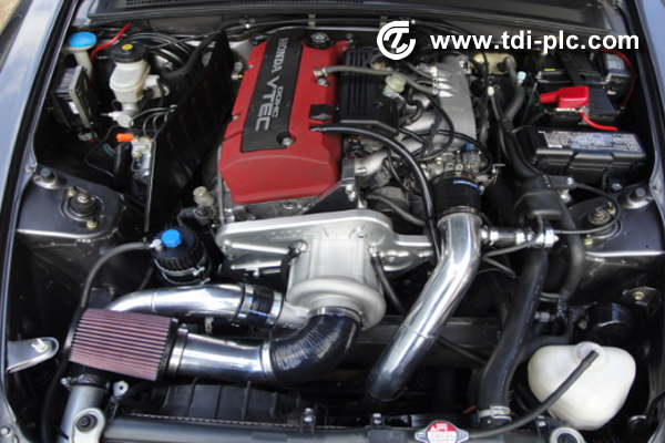
Here is my intake setup. The K&N filter is brand new, and quite big.
My intercooler is quite small however: about 17,7 x 6,5 x 3,5" core size.
My IATs seem high (about 45°C with 10°C outside) but I suspect my IAT sensor to suffer heatsoak actually (AP1 stock IAT sensor, in the manifold).
So you say 8 psi can ben a "normal" number for the total pressure loss in the hole system ? I thought it was more like 3 psi...
I will try the maths of your link later.
Remember to calculate pressure ratio. The air filter looks pretty low restriction, but the greater the intake restriction, the more it reduces your positive intake manifold pressure. Once you make the calculator, you can play with different intake restriction numbers and see what it does to your manifold pressure. A good flowing IC system is like 2-3psi, a bad one can be double. Is there shielding underneath the air filter? If not, it's sucking in hot air off the radiator which is further reducing the corrected mass flow which brings you further backwards down the boost curve. Again, you can play with compressor inlet air temps and see what that does to your corrected mass flow. Last thing is you might have a small boost leak somewhere.
Thank you so much for your help ! I really wan't to make that math work, and you are getting me on the route for it !
I will complete my worksheet to take in consideration the inlet temperature, the intake pressure drop.
Yes my filter has a complete shielding including underneath, just like a K&N FIPK actually.
Here is a picture while I was building it:
Building thread here :https://www.s2ki.com/forums/s2000-fo...nside-1196634/
I have been wanting to leak test my piping and IC for a long time, but I don't have the required equipment. And my boost curve is quite linear on logs: I supposed that a boost leak would make the curve "slower" at high rpm/boost and show me the leak.
Honestly: you are making me thinking of changing my IC haha! The maker of the kit (TTS Performance) told me that it was the ("volonteer") restricting part of my kit, and my tuner said it was not efficient (only regarding my high IATs, which I think is more a heatsoak problem). This math is making one more reason to change it !
Hmm..... looking at your intake setup. The carbon fiber duct does look to go over the radiator. Is it a 'tube' that goes over radiator? Or is it U-shaped with the bottom open to the radiator? The air actually picks up a lot of heat off the top of the radiator if the air is in contact with the metal surface. I take it your intercooler is in the front bumper opening. The IC on that side of the car is hot. So air goes over/around the IC which is hot and then up to the duct feeding the air filter.
You are right again: my carbon duct is U shaped, so the uper face of the radiator is in contact with the intake air. However, I wouldn't have thought that such a small and flat surface would heat air that much, especially with that high flow/velocity or air.
Here is a detailed view of that part:
And here is my intercooler, of course installed in front of the bumper opening:
As my IC is not very big, some air can actually pass on the sides and the top of the IC. But yes, the IC is warming a bit the air that then goes to the intake duct.
I absolutely don't want to make any serious modification to my hood or bumper, so a NACA duct will not be possible for me.
What I could do is try to make a duct coming from the gap on th left of my IC, to the carbon duct, to help feeding cold air instead of IC-warmed air ...
I really understand those points and will try to take care of them to improve my setup. But honestly, I thought I had already made somethnig correct with the custom shields and the carbon duct. When I compare to "basic" Kraftwerks or TTS setups, that have nothing to feed cold air, I don't understand why people don't have IAT issues...
You could also move where you feed air to your box. Instead of the stock air intake flow of air entering from above radiator, feed it from the large fender opening that is in front of the shock tower. The air will be much cooler than air that picked up heat from IC and or radiator.
You could even make the bumper fake duct into a real duct, then pipe the air to your box via a flex hose from bumper duct all the way to filter, hidden behind bumper and fender. There is space back there for such a hose to route without any hard turns.
You are right again: my carbon duct is U shaped, so the uper face of the radiator is in contact with the intake air. However, I wouldn't have thought that such a small and flat surface would heat air that much, especially with that high flow/velocity or air.
Here is a detailed view of that part:
As my IC is not very big, some air can actually pass on the sides and the top of the IC. But yes, the IC is warming a bit the air that then goes to the intake duct.
I absolutely don't want to make any serious modification to my hood or bumper, so a NACA duct will not be possible for me.
What I could do is try to make a duct coming from the gap on th left of my IC, to the carbon duct, to help feeding cold air instead of IC-warmed air ...
I really understand those points and will try to take care of them to improve my setup. But honestly, I thought I had already made somethnig correct with the custom shields and the carbon duct. When I compare to "basic" Kraftwerks or TTS setups, that have nothing to feed cold air, I don't understand why people don't have IAT issues...
I was surprised too at how much heat was picked up off the top of the radiator. Data doesn't lie though, 7degC. You can put some type of insulation material on top of the radiator just where the duct is to reduce the heat transfer. You have lots of air gap around your IC, so you can use 2" neoprene brake duct hose on both sides of the IC to direct air to the carbon duct which would be minimal modification. Or at least your driver side, which I noticed your car is RHD, but you're in France... they never sold the S2k in France?
And who says the Kraftwerks and TTS setups don't have issues They probably just don't measure. Keep in mind, the Kraftwerks kit is known to be highly unreliable. They might be over-spinning the blower to compensate for the hot air leading to the failures.
I will try to improve my intake as you say , with two possibilities:
- insulating the top of the radiator with some foam, and making a plate to close the "U-shape" duct in a closed [squared duct
- routing some fresh air duct from the side of the intecooler
I alreday own a set of AP1 bumper brake duct inlets, but still did not install them because the IC piping is just behind and it will touch... and in my heart, I would like to keep my bumper uncut.
Yes my car is RHD. S2K has been sold in France of course, from 1999 to 2009, but the prices of the used cars are much cheaper in UK, so a lot of french people have imported UK cars, which is easy legal and easy to do. Importing a US or JPN car is much more job and money, unfortunately.