When you click on links to various merchants on this site and make a purchase, this can result in this site earning a commission. Affiliate programs and affiliations include, but are not limited to, the eBay Partner Network.
Install of AEM Fuel Pump and ScienceofSpeed Wiring Kit
Hi everyone,
I recently purchased an AEM Fuel Pump and the single pump wiring kit from ScienceofSpeed. Great products. I already fitted the new pump into the carrier, and once I started looking at the instructions, I realized that I needed to upgrade my wiring tools. I would like to an install thread with photos beginning this weekend, but I'd like to ask a question first.
I just received an insulated terminal crimper (Tool Aid 18900) and a open barrel double rolling crimper (Eclipse 300-005) as recommended by the instructions through Amazon. I also received an auto terminal release tool set which I decided to finally buy, rather than playing around with paper clips (my ghetto tool throughout the years).
I am going to begin with modifying the in-tank electrical harness with the wire harness provided with the AEM pump. I understand what the instructions state, but my paranoia kicked in (despite my last change of the fuel filter which led me to conclude that my OEM pump went bad). Is this wiring ever exposed to gasoline? As in, given that its the in tank wire harness, does the harness ever sit in the gas? I imagine so, or that the gasoline may slosh around and wet the wire harness while driving. It this correct? How does the gas not ignite with current flowing through the wiring inside the tank? The instructions state to use the non-insulated crimper which suggests to me that the wires are exposed to the gas.
Please weigh in guys. I am going to begin the photo project to post on here this weekend.
The wires do sit in the gas. You should have noticed the extra grounding wire on the factory in tank wiring. I added that wiring to the supplied wires with the pump, as I like the idea of an extra path to ground inside the tank. I personally soldered all of my wires.
As for the gas igniting with the wires sitting in the tank, highly unlikely. Unless something were to short to ground and create a spark this is not an issue to be worried about.
Thank you very much. I did notice the ground cable and that I had to swap it over to the AEM harness. I was curious as to whether it was grounding to the gasoline itself, because I believe that plastic does not conduct electricity?
The sos instructions tell you to cut the thin ground wire off the aem pump, then to rewire it into the "other" ground wire that goes into the connector which ultimately you would plug into the fuel pump carrier, so why not NOT cut the wire to begin with and just connect the static ground wire to the carrier? Why cut and reconnect the ground that appears to be going to the same location? does it matter if you just wire it up without relocating that thin ground wire?
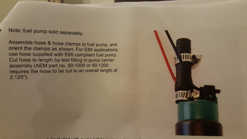
Here are the instructions from sos:
Hey guys, sorry haven't got around to this earlier. Here goes:
This is the trunk with the interior taken out. You will have to bend yourself down and get deep into the trunk which is pretty uncomfortable. You will have to remove the piece of interior plastic that the top rests upon when down by removing from the trunk side.
I had already taken the fuel pump out before I started taking photos. Below you will see the tank with the pump taken out. In addition to the three screws holding the upper plate in place, you will have to unplug the fuel pump and remove another plate with about 8 bolts. You will also see a cable in the lower left corner which will need to be taken out of the way before removing the pump. You can see where the bolt went. It's best to have a second person guiding you, who is looking downward through the rear window.
Below you will see the pump removed. I already removed the plug that will need to be modified.
The black tubing will have to be removed before the pump is taken out, along with the plastic cap at the bottom. It has a rubber piece inside of it that holds the pump still.
This is the stock pump removed from the pump carrier.
The SOS instructions recommended this double barrel non insulated terminal crimper
and this insulated terminal crimper
I also bought a set of these depinning tools for the connectors that need to be modified.
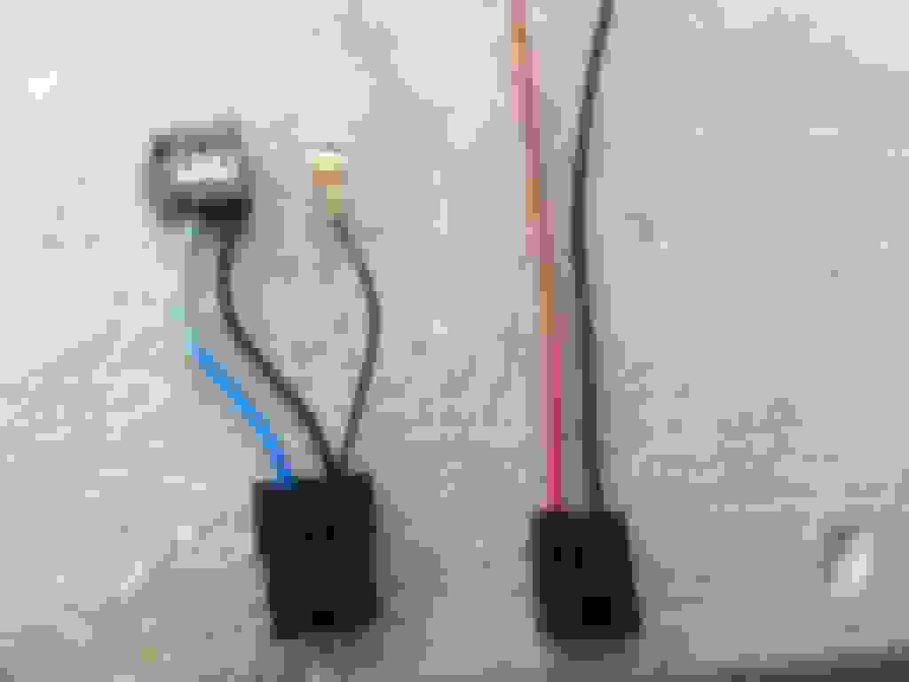
The stock wiring is on the left and the new plug is on the right. The new plug has thicker gauge wiring.
The clip retainer is popped out by prying the retainer from the top like so
This is the plug with the retainer removed.
When you stick the tool underneath the plastic as shown, the pin will come right out by pulling from the wire.
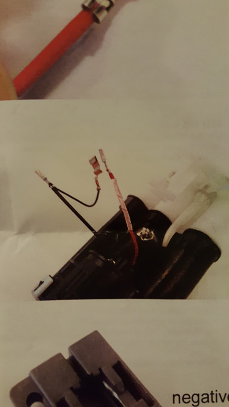
So, I cut the red and black wire from the new plug to be a bit shorter than the stock length. I installed the pins specified in the instructions, and connected the exposed group wire to the top plug, as opposed to the bottom plug in the stock configuration.
This is the connector that plugs into the top of the fuel pump carrier. I popped the rear cap off from the three tabs with the depinning tool.
The blue face comes off by using the depinning tool to pry it off from the depression on the side of the face next to my thumb there.
Here, you can see the second piece of power wire connected to its respective slot in the relay connector, after the relay terminal was installed. I have the relay shown as it will go into the connector. (I ended up needing to purchase a bosch 30 amp relay after the bueller relay went bad on me.).
The thick grounding wire will have this end crimped on and will be attached to a bolt in the trunk. I used sanding paper to remove the paint from the grounding spot.
The two top slots are empty in this pic, shown after removing the pins.
These are the power and ground cable removed from the pump connector. The will serve as a switch signal for the relay.
These are the two wires after being pulled out from beneath the cover plate.
Relay terminals installed.
These are the new power and ground wires with pins attached, ready for insertion into the plug.
The wire will go into the connector through the back as shown.
These are the power and ground installed into the rear of the connector. The red shrink wrap was added because I almost cut the wire too short. The coating was not pierced, but I figured it best to wrap it in case it wears down over time.
Capped down.
Face installed.
Plugged into the top of the pump carrier.
Capped down. These wires are later covered in loom and then wrapped in electric tape.