My Vortech S/C install guide!
 04-30-2006, 01:58 AM
#11
Member


Thread Starter
Right - Quick update as ive been in Aberdeen on business all week 
Doing the pulley and mounting FMU tomorrow! Then next weekend ive alloted a fair bit of time to finish the job off. Bit optimistic maybe, but im going to giv it a go. Got all the oil / coolant / wiring ready to go! Not got any new plugs yet but will see how the standard one's behave.
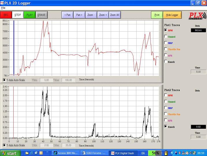
Here are some of the graphs from the PLX so I can gauge what the AFR and knock were doing. The screen is split into 2 windows and you can have multiple variable on them.
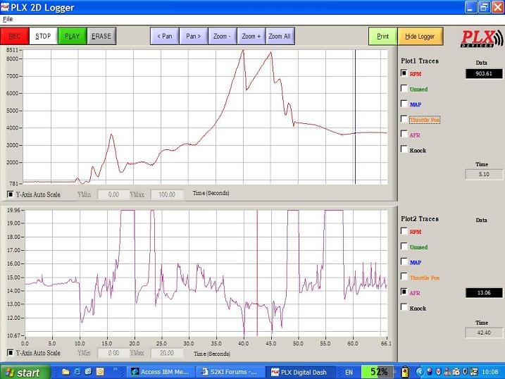
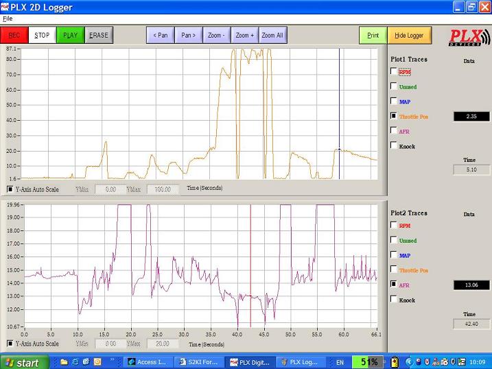
The 1st one shows RPM against knock, and the second one shows RPM against AFR and the final one is Throttle pos against AFR. Surprising how lean these cars run at part throttle... I basically got idle as 14.5 ish and WOT about 13 - the bits where is goes to max (20) is just on lift off of the throttle as the injectors close here.
All I did to do this was set the PLX to record and then went and had some fun! Also let the car idle and stuff just to see what the closed loop lambda control looked like (should bounce back and forward)
Any questions let me know!
Oh, ive also got an interesting one of the MAP voltage in "kangeroo" mode - i set it to record in traffic and luckily caught some data!
MB
Doing the pulley and mounting FMU tomorrow! Then next weekend ive alloted a fair bit of time to finish the job off. Bit optimistic maybe, but im going to giv it a go. Got all the oil / coolant / wiring ready to go! Not got any new plugs yet but will see how the standard one's behave.
Here are some of the graphs from the PLX so I can gauge what the AFR and knock were doing. The screen is split into 2 windows and you can have multiple variable on them.
The 1st one shows RPM against knock, and the second one shows RPM against AFR and the final one is Throttle pos against AFR. Surprising how lean these cars run at part throttle... I basically got idle as 14.5 ish and WOT about 13 - the bits where is goes to max (20) is just on lift off of the throttle as the injectors close here.
All I did to do this was set the PLX to record and then went and had some fun! Also let the car idle and stuff just to see what the closed loop lambda control looked like (should bounce back and forward)
Any questions let me know!
Oh, ive also got an interesting one of the MAP voltage in "kangeroo" mode - i set it to record in traffic and luckily caught some data!
MB
 04-30-2006, 01:58 AM
#12
Member
Thread Starter
All the PLX is doing is showing me my air fuel ratio from a separate lambda sensor, but its got much better resolution. The other thing its doing is tapping into some of the key sensors in the car. When I press record it starts logging all the data from these sensors. All the sensors are 0-5v so the throttle position for example, is 0.4v closed and 4.5v open (roughly) so thats its 0-100%
The software shown above justs lets you trend all the different things you want so you can see how the car is behaving.
The key bits im interested in are the air fuel ratio (AFR) and knock from the knock sensor. Stoich AFR for normal gasoline is 14.7 parts to 1 and thats described as a perfect burn. you can be a bit either side of that with no real issue. With AFR a low number is Rich and a high number is Lean - ie 20 on my chart above.
Running lean does give more power, but too lean and your fuel starts to predetonate and causes all sorts of bad engine internal issues! so thats what I need to avoid with the blower on there.
There are 2 types of modes that the lambda sensor uses on these,and many cars. At idle and part throttle or on cruise the ECU is using the lambda sensor to judge the fuelling and it bounces a bit either side of stoich trying to find an even burn. This is called closed loop lambda control. Its quite an efficient method of controlling fuelling.
Open loop lambda control is when you put your foot flat to the floor (WOT or wide open throttle) - the MAP sensor takes over the fuelling and its here, or high revs that you are most likely to encounter det, and the place you least want to run lean on fuel. Which kind of goes hand in hand. At this point the lambda sensor goes passive and has no input. the ECU is using the MAP sensor to calclate the engine load, and uses pre programmed fuelling profiles that are written into the ECU programming.
If you look at the RPM vs AFR trend above you can see what the fuelling is doing and how it changes with RPM and throttle position.
A good example is when you can see ive let the throttle off, and its closed. The injectors close and therefore the lambda sensor is seeing mostly air - and the AFR goes to max of 20.
Sorry thats all long winded but hopefully if you have a read it will become a bit clearer!
MB
04-30-2006, 02:00 AM
#13
Member
Thread Starter
Ok, been a bit lazy this weekend but I want to get the S/C pulley on.
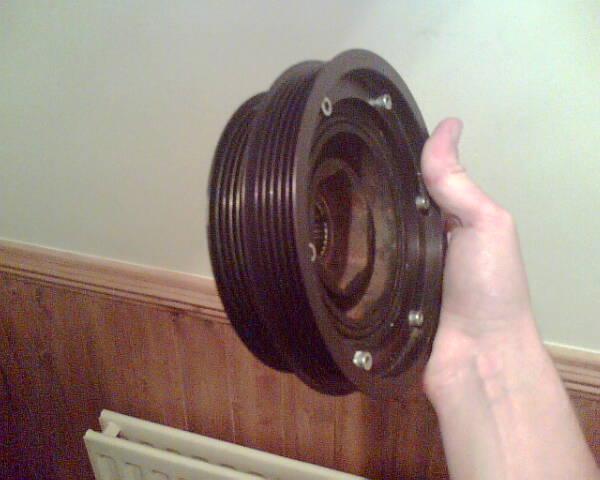
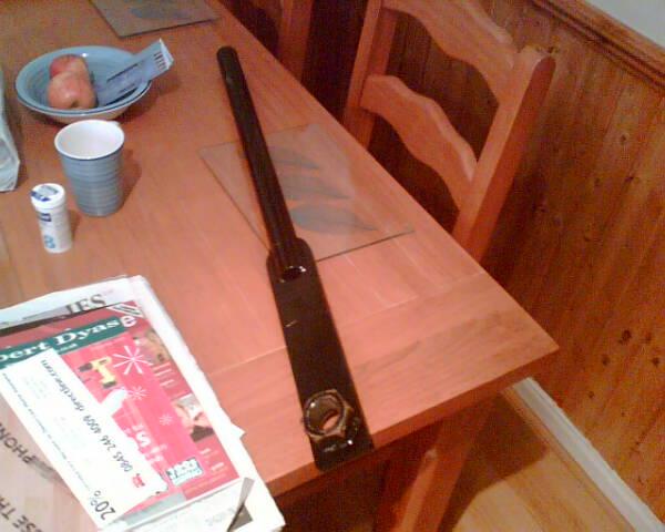
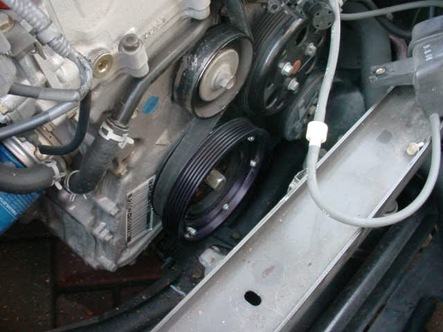
Here's the new pulley, which is a double one therefore allows the original belt to be driven and also the S/C.
Here the big tool for removing the existing pulley
Today I got a reasonable amount of the SC done, and have loaded up the pulley pics so here comes the write up as usual! Today taught me that it is so important to have all the right bits and a clear idea what you're trying to achieve. I thought this through pretty well hence the time its taken. What you dont see on this write up is all the gathering of info from people, sourcing of Loctite, buying tools I didn't have etc... it really does take some thinking. Reading the S/C manual over and over is helpful too.
Tomorrow I will finish the SC off, fit the Aftercooler, and also fit the intake. I will do the fuel lines, FMU and the engine management wiring in the week all being well!
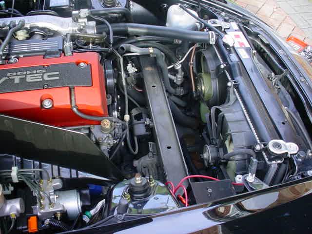
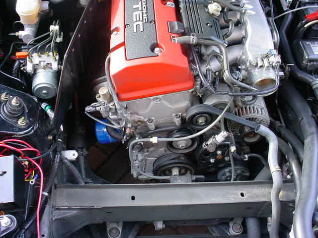
Ok, the pulley first - you need to remove this to add the Vortech one, which is a double and allows space for the S/C belt to go on, to drive the S/C itself. It was a bit of a bugger this and the right tools are really essential. You have to remove all the intake box including the pipe upto the throttle body, and all the little vac hoses and coolant pipes too. All gone! There's a vacuum box bolted to the chassis that is moved temporarily too. All very easy and as per the manual.
Here's the airbox out and you can see the pulley that needs to be removed:
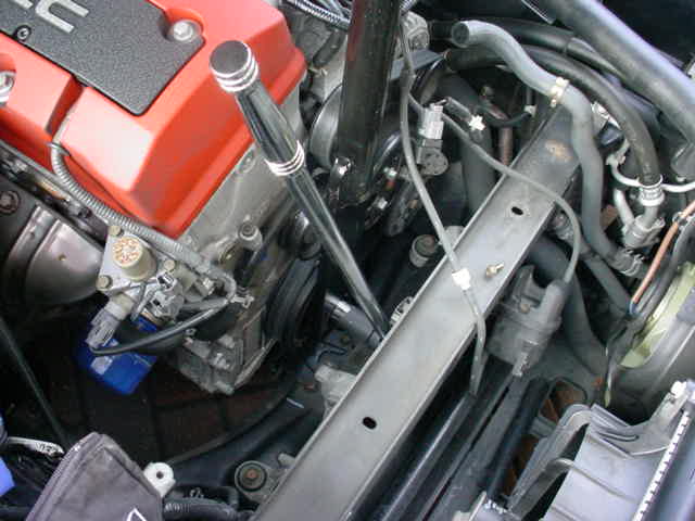
To remove the pulley itself I would advise dousing it with Plus Gas or Release a day or 2 before hand. Then you need the pulley holder tool pictured earlier in this thread. This goes over the pulley nut (its a hex head) and allows you to keep the pullet from turning when you undo the nut. Totally esseantial tool. To undo the nut you need a 1/2" or 3/4" breaker bar with a 1/2 drive on the end. You then need an impact socket (must be an impact socket to get better drive) of 19mm. The pic below shows the pulley holder and breaker bar in place. I actually moved the pulley holder tool down onto the wing and had loads of cushioning on it. I then put the breaker bar socket on the pulley, and a 5 foot scaffold. You basically have to lever them apart!
Pulley off and new one goes on. The old one just slides off and is key driven. New one needs torquing to 181 lbs/ft.
The S/C has its own VTEC solenoid arangement so the old one all comes off (crap pic) You can see it on the top left of the engine.
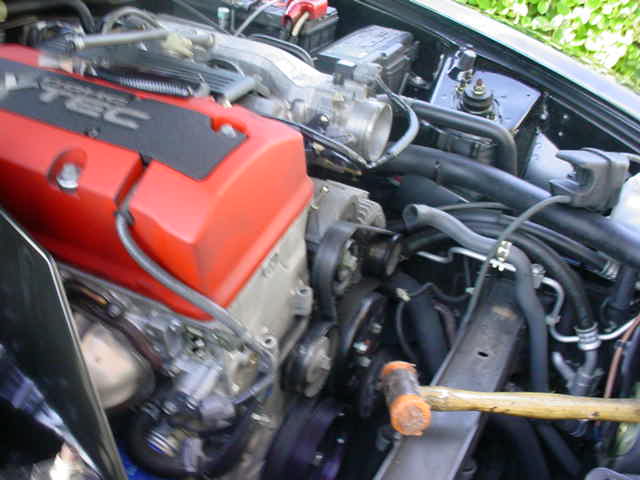
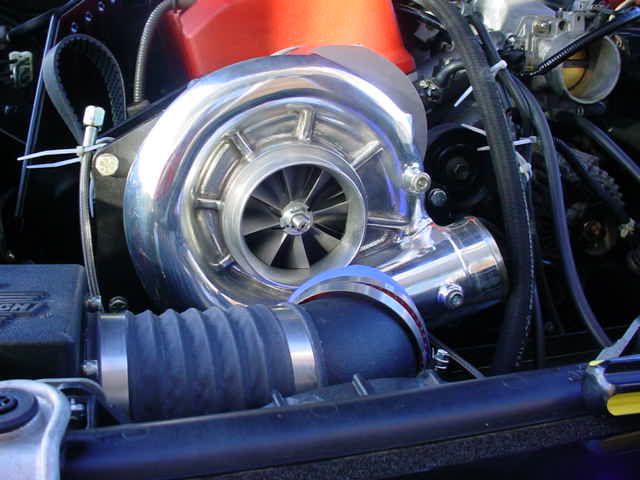
Ok, so once you've done that you can put the blower on! This is where it gets exciting. You have to assemble the whole supercharger to the mounting bracket assembly. On the pic of the new pulley above, you can see ive removed 2 bolts on the left of the sticker on the block. Theres some long threaded bolts that go in here and a solid mounting plate that goes over it. That supports the bottom of the blower. You can see it as a big black flat block on the bottom 2 pics, under the belt. I've loosely put the blower belt onto the assembly and mounted it on the engine bay!
Not finished bolting it up but at least its on! The only bother I did have, and I was lucky to spot it, was the jubilee clip on the oil filter shown below. It was sticking out horizontally and would have interfered with the S/C idler pulley.
I moved it out the way
So what now??? Ive got some pics of the oil feed to come and tomorrow will set about getting the car temporarily driveable. That means fitting the intake, aftercooler, refitting vac lines etc, and mouting the S/C properly. I will blank off the oil feed return as im not ready to do the sump yet. I will drive it without the pulley on which means I dont have to do the fuel bits yet.
It will just about suck air through that lot, and i will take it v steady...
More to come tomorrow!
MB
Here's the new pulley, which is a double one therefore allows the original belt to be driven and also the S/C.
Here the big tool for removing the existing pulley
Today I got a reasonable amount of the SC done, and have loaded up the pulley pics so here comes the write up as usual! Today taught me that it is so important to have all the right bits and a clear idea what you're trying to achieve. I thought this through pretty well hence the time its taken. What you dont see on this write up is all the gathering of info from people, sourcing of Loctite, buying tools I didn't have etc... it really does take some thinking. Reading the S/C manual over and over is helpful too.
Tomorrow I will finish the SC off, fit the Aftercooler, and also fit the intake. I will do the fuel lines, FMU and the engine management wiring in the week all being well!
Ok, the pulley first - you need to remove this to add the Vortech one, which is a double and allows space for the S/C belt to go on, to drive the S/C itself. It was a bit of a bugger this and the right tools are really essential. You have to remove all the intake box including the pipe upto the throttle body, and all the little vac hoses and coolant pipes too. All gone! There's a vacuum box bolted to the chassis that is moved temporarily too. All very easy and as per the manual.
Here's the airbox out and you can see the pulley that needs to be removed:
To remove the pulley itself I would advise dousing it with Plus Gas or Release a day or 2 before hand. Then you need the pulley holder tool pictured earlier in this thread. This goes over the pulley nut (its a hex head) and allows you to keep the pullet from turning when you undo the nut. Totally esseantial tool. To undo the nut you need a 1/2" or 3/4" breaker bar with a 1/2 drive on the end. You then need an impact socket (must be an impact socket to get better drive) of 19mm. The pic below shows the pulley holder and breaker bar in place. I actually moved the pulley holder tool down onto the wing and had loads of cushioning on it. I then put the breaker bar socket on the pulley, and a 5 foot scaffold. You basically have to lever them apart!
Pulley off and new one goes on. The old one just slides off and is key driven. New one needs torquing to 181 lbs/ft.
The S/C has its own VTEC solenoid arangement so the old one all comes off (crap pic) You can see it on the top left of the engine.
Ok, so once you've done that you can put the blower on! This is where it gets exciting. You have to assemble the whole supercharger to the mounting bracket assembly. On the pic of the new pulley above, you can see ive removed 2 bolts on the left of the sticker on the block. Theres some long threaded bolts that go in here and a solid mounting plate that goes over it. That supports the bottom of the blower. You can see it as a big black flat block on the bottom 2 pics, under the belt. I've loosely put the blower belt onto the assembly and mounted it on the engine bay!
Not finished bolting it up but at least its on! The only bother I did have, and I was lucky to spot it, was the jubilee clip on the oil filter shown below. It was sticking out horizontally and would have interfered with the S/C idler pulley.
I moved it out the way
So what now??? Ive got some pics of the oil feed to come and tomorrow will set about getting the car temporarily driveable. That means fitting the intake, aftercooler, refitting vac lines etc, and mouting the S/C properly. I will blank off the oil feed return as im not ready to do the sump yet. I will drive it without the pulley on which means I dont have to do the fuel bits yet.
It will just about suck air through that lot, and i will take it v steady...
More to come tomorrow!
MB
04-30-2006, 02:01 AM
#14
Member
Thread Starter
What a day
I worked from 10am until about 7pm and skipped lunch. Im sore - tired and in a bit of a mood
Today's task was to harden down all the S/C bolts so it was totally fixed in place and to fit the aftercooler and intake, to allow me to drive the car.
Started by tightening up all the S/C bolts.
Now, if you are doing this yourself - fit the bloody oil supply before you fit the VTEC solenoid support / extension! You can see it in the pic below, its the black block / spacer between the engine block and the VTEC soleniod. The oil supply is under this and its a total bastard to get to with all that in place. Do the oil feed first is my advice!
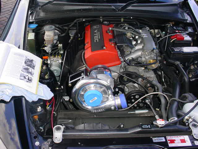
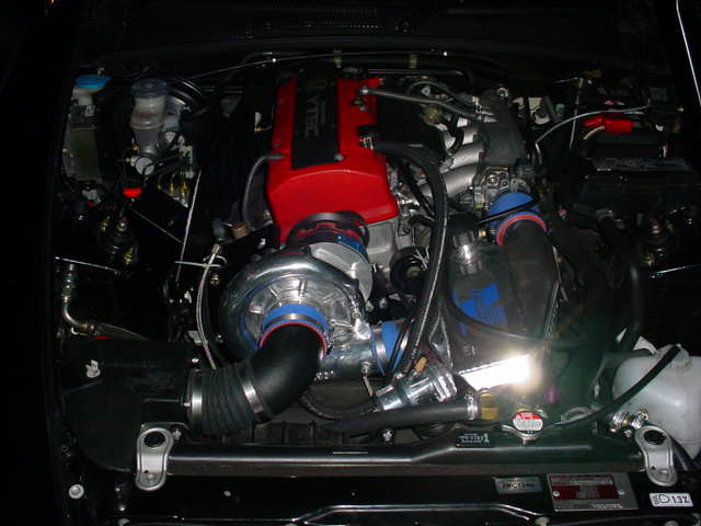
Once I had got all that sorted I was ready to do the aftercooler. Now I have already fitted the new radiator / coolant pump / and reservoir early in thie thread. So I have 2 hoses up in the engine bay waiting for the aftercooler to be fitted. This is very straight forward so im not putting much info in about this. Here it is fitted:
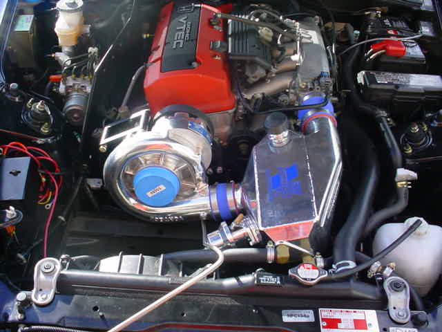
Now that's done I can fit the Intake. Its immediately obvious that there's some things in the way here! the alarm for one, and a connector that sits on the left hand fan, and also the stock air box bracket down on the cross member. Here's a pic:
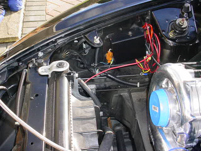
Moved / rerouted the bits mentioned above. The alarm is now further up in the engine bay. Airbox is very easy to fit. I am surprised ive not seen more issues with fitting, as this kit is menat for American left hookers. Some of the FMU and other wiring will be a bit different.
Ok, got all that fitted and here it is all done! Ive left the belt off and all seems ok apart from Ive got a check engine light, and I think I know what it is. The solenoid that used to live on the airbox - I connected it up wrong!
Frightening amount of tools involved in this, and it really isnt for the feint hearted. Right now I wish i had stayed N/A but im sure it will be worth it. It looks straight forward but some of it is very fiddly, and the pics in the manual could be better.
Now, one thing I have to mention (hence my annoyance today) is that I connected up the oil feed and intended to do the drain too. I decided by tea time to do it another day and blocked off the oil return with a plug. Due to what I can only put down to tiredness, I later moved the car off the driveway. Quite a large oil leak appeared I knew straight away what it was - the return line had built up pressre and had nowhere to go but out the blower casing. The car cant be driven in that way which I knew, but forgot! Die to other problems, I then needed to use the car tonight - so I had 2 options. Fit the spare sump with the oil return fitting meaning the blower had oil flow, or removing the oil feed.
To do the pan would have been a new job and there could have been issues, so I chose the remove the oil feed and have no oil to the S/C - ok as I dont have the belt moving it. This was a bastard to undo. Basically the VTEC soleniod that goes into the block now has an extension / adapter to allow the S/C to tap its oil feed into. had to remove all this (very fiddly) and return it to stock.
Ah well
Drove the car home, no leaks, took it steady but the car sounds reasonably happy sucking air through the stationary blower!
MB
I worked from 10am until about 7pm and skipped lunch. Im sore - tired and in a bit of a mood
Today's task was to harden down all the S/C bolts so it was totally fixed in place and to fit the aftercooler and intake, to allow me to drive the car.
Started by tightening up all the S/C bolts.
Now, if you are doing this yourself - fit the bloody oil supply before you fit the VTEC solenoid support / extension! You can see it in the pic below, its the black block / spacer between the engine block and the VTEC soleniod. The oil supply is under this and its a total bastard to get to with all that in place. Do the oil feed first is my advice!
Once I had got all that sorted I was ready to do the aftercooler. Now I have already fitted the new radiator / coolant pump / and reservoir early in thie thread. So I have 2 hoses up in the engine bay waiting for the aftercooler to be fitted. This is very straight forward so im not putting much info in about this. Here it is fitted:
Now that's done I can fit the Intake. Its immediately obvious that there's some things in the way here! the alarm for one, and a connector that sits on the left hand fan, and also the stock air box bracket down on the cross member. Here's a pic:
Moved / rerouted the bits mentioned above. The alarm is now further up in the engine bay. Airbox is very easy to fit. I am surprised ive not seen more issues with fitting, as this kit is menat for American left hookers. Some of the FMU and other wiring will be a bit different.
Ok, got all that fitted and here it is all done! Ive left the belt off and all seems ok apart from Ive got a check engine light, and I think I know what it is. The solenoid that used to live on the airbox - I connected it up wrong!
Frightening amount of tools involved in this, and it really isnt for the feint hearted. Right now I wish i had stayed N/A but im sure it will be worth it. It looks straight forward but some of it is very fiddly, and the pics in the manual could be better.
Now, one thing I have to mention (hence my annoyance today) is that I connected up the oil feed and intended to do the drain too. I decided by tea time to do it another day and blocked off the oil return with a plug. Due to what I can only put down to tiredness, I later moved the car off the driveway. Quite a large oil leak appeared
I knew straight away what it was - the return line had built up pressre and had nowhere to go but out the blower casing. The car cant be driven in that way which I knew, but forgot! Die to other problems, I then needed to use the car tonight - so I had 2 options. Fit the spare sump with the oil return fitting meaning the blower had oil flow, or removing the oil feed.To do the pan would have been a new job and there could have been issues, so I chose the remove the oil feed and have no oil to the S/C - ok as I dont have the belt moving it. This was a bastard to undo. Basically the VTEC soleniod that goes into the block now has an extension / adapter to allow the S/C to tap its oil feed into. had to remove all this (very fiddly) and return it to stock.
Ah well
Drove the car home, no leaks, took it steady but the car sounds reasonably happy sucking air through the stationary blower!
MB
04-30-2006, 02:02 AM
#15
Member
Thread Starter
Seems like good news on my blower. Understand the sealing arrangement a bit better and will finish the supply and return off this weekend! It may leak, it may not but I will not have damaged the seal from what happened IMO.
One point of note - Vortech are totally useless at customer service and repeatedy told me it would have to be overhauled at $500. Weren't interested in helping with the problem. I emailed them weeks ago about something else and got a crap reply.
Comptech seem far better at this... I would seriously think about their unit over this one for that reason, and the oil return is much easier. I also like the fact it produes a bit less power.
This oil bit has pissed me off a bit and I was close to jacking it all in and buying some nice wheels and some ICE - but I will plod on There are a few more potential hurdles to come though!
The main headaches will be:
Any oil leaks
Coolant leaks - easy to sort though
Fuelling problems (FMU / spark plugs etc)
Fuel managment box not working
Hopefully it will all work!
MB
One point of note - Vortech are totally useless at customer service and repeatedy told me it would have to be overhauled at $500. Weren't interested in helping with the problem. I emailed them weeks ago about something else and got a crap reply.
Comptech seem far better at this... I would seriously think about their unit over this one for that reason, and the oil return is much easier. I also like the fact it produes a bit less power.
This oil bit has pissed me off a bit and I was close to jacking it all in and buying some nice wheels and some ICE - but I will plod on
There are a few more potential hurdles to come though!The main headaches will be:
Any oil leaks
Coolant leaks - easy to sort though
Fuelling problems (FMU / spark plugs etc)
Fuel managment box not working
Hopefully it will all work!
MB
04-30-2006, 02:03 AM
#16
Member
Thread Starter
I got so wasted on Thurs I spent the next day in bed. Trying to prove I could down 2 pints of stella in a row must have been the point it all turned bad!Today I took the whole blower off and checked it for leaks. Ive got some pics to come of what I did and what fittings I resealed. Will put them up tomorrow. Didnt get time to hook up the supply and do the oilpan.
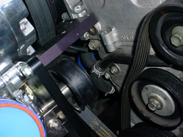
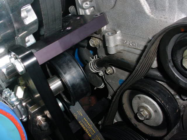
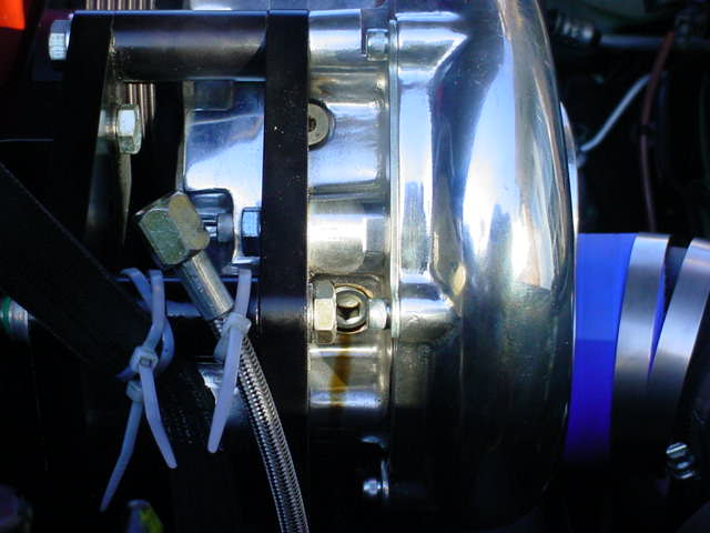
Going back to the pulley - V important note for anyone doing this, which is also highlighted in X Viper's post - The idler pulley you can see below has to come off too, which is very easy to unbolt. On the front of it there is a dust cap which you can see, being held on by the bolt. Behind that is a washer and then a bearing and sleeve that goes through the pulley. The Vortech manual says use none of this, which is not what you should do! You must use the bearing and sleeve, but not the dust shield and washer. It wont turn if you listen to them!
I will get a better pic of it with the S/C on, but basically you put a long bolt through the S/C bracket then through the idler pulley pictured above, and it acts as one of the supports for the whole thing.
Tonight im on the lash too so tomorrow will also be a write off!
Next weekend it is then...
One more point, I can really feel the weight on the front of the car. its not massive but I am noticing it.
MB
04-30-2006, 02:04 AM
#17
Member
Thread Starter
Just some more pics of my leaking blower! I took it all off to make sure I hadn't missed anything.
First I wanted to check the inlet and outlet for any oil as that would mean a bad leak.
Took the outlet off and all clean - that bit of oil was me!
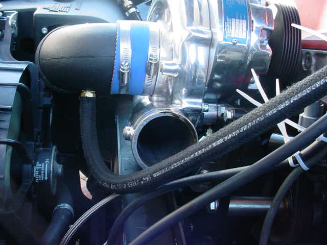
Inlet clean too - you can see the oil feed line tied up in the background
The offending cap head plug on the side - you can see a bit of oil leaking
Took it out and put a load of hard setting sealant on it!
Pray thats fixed it! That plug looks into the internal gears so not too fussed about a leak that side, its just not meant to take pressure!
PS - excuse the tie wraps, just a temporary measure!
MB
First I wanted to check the inlet and outlet for any oil as that would mean a bad leak.
Took the outlet off and all clean - that bit of oil was me!
Inlet clean too - you can see the oil feed line tied up in the background
The offending cap head plug on the side - you can see a bit of oil leaking
Took it out and put a load of hard setting sealant on it!
Pray thats fixed it! That plug looks into the internal gears so not too fussed about a leak that side, its just not meant to take pressure!
PS - excuse the tie wraps, just a temporary measure!
MB
04-30-2006, 02:05 AM
#18
Member
Thread Starter
Ok,
Yesterday I attempted to do the sump and realised I didnt have the right equipment or patience to do it. At that point I actually decided id had enough and convinced myself I was jacking it in - my last few weekends have been spent on the car
Woke up today and am a bit 50/50 - there's not far to go and its not that hard to finish, ive just run out of patience! The sump really needs a pit / car lift as I found it too tricky to do under axle stands. Guess I should have just taken a week off and done it all at once.
Will probably ring Honda Monday and just get them to do it later in the week. Will cost a bit but its that or I give up! Im sure the end result will be worth it....
After that all there is to do is connect the oil feed back up, wire up the coolant pump to the fuse box, and fit the fuel management unit.
Im going to get Honda to do it
Bear with me though!
MB
04-30-2006, 02:07 AM
#19
Member
Thread Starter
Ok the oil pan is now finished thanks to Honda in Bournemouth. My only gripe is that I asked them to re use my fresh charge of Motul but they binned it by mistake! At least they told me and nocked it off the bill. One of the reasons I hate getting anyone to do anything on the car. Just over
04-30-2006, 02:08 AM
#20
Member
Thread Starter
Well it doesnt leak!
I got the whole oil system hooked up and working today so im quite chuffed at that, and that it all works!
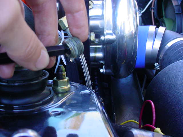
Here's how the oil supply is hooked up, not too tricky apart from putting the new adapter in place.
Note, the manual says dont use any thread sealant, but im buggered if im following that advice! I used a touch of loctite on the threads to make sure. Their concern is that some selant may come off and bung up the SC oilways....
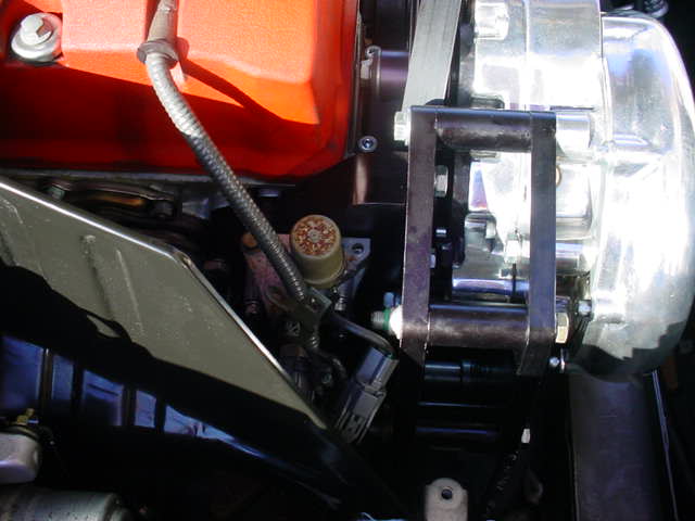
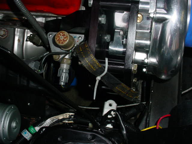
Ok, in this pic you can see the oil feed braided hose that needs to go into the block under the VTEC solenoid assembly that you can see (its the assembly with the rusty lid on it) You can see that it it used to go straight onto the side of the block, but now it has the big plack piece sandwiched in the middle, which is part of the support for the supercharger.
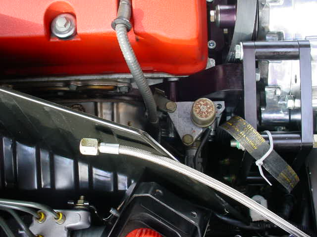
Best to remove 3 bolts on the heatshield and tilt it upwards, that allows you to get onto the 2 allen bolts. You need an allen key with a head on it that allows you to unbolt at an angle, or you will be there all day Unclip the sensors from the VTEC assembly.
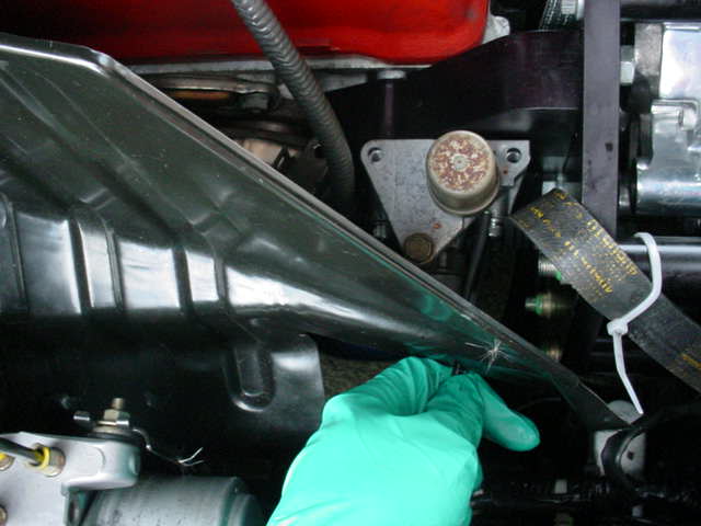
VTEC assemblt removed, you can see the rubber O ring which seals up against the SC support bracket. Underneath the support bracket is the oil pressure sensor, which is threaded into the block. Removed with a 15/16 socket.
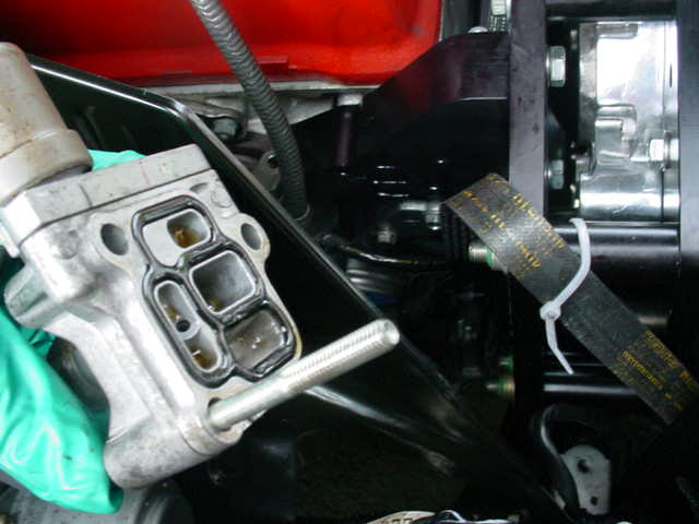
Here's the pressure sensor out.
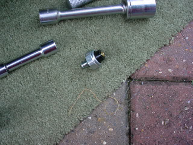
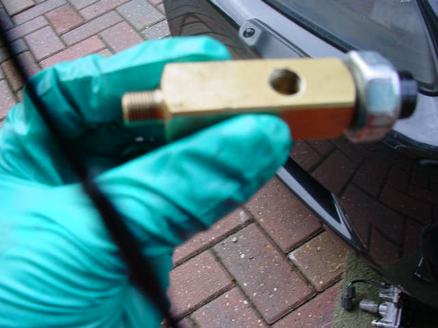
Here it is in its new home. Its basically an adapter so the pressure sensor can bolt into the end, then the adapter goes into the block where the sensor used to go. Also has the threaed hole for the SC oil supply.
Now installed into the block, and the elbow that allows the oil hose now in place too.
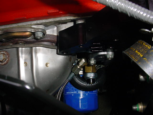
And all back together again! No leaks....
I also mounted the FMU in the engine bay, ready for the fuel hoses to go on. This is the part that alters the fuel pressure. Also placed the Vortech timing / map controller in the passenger footwell and ran the boost hose through the bulkhead ready for mounting. Filled the aftercooler with coolant and hooked up the electrics apart from the live. Not redy to start it yet! Pics of all that to come.
So not much to do now!
I got to hookup the FMU which is pretty straight forward, put the new spark plugs in, wire in the Timing / Map controller (tricky) and then put the belt on! I can see the light at the end of the tunnel
MB
I got the whole oil system hooked up and working today so im quite chuffed at that, and that it all works!
Here's how the oil supply is hooked up, not too tricky apart from putting the new adapter in place.
Note, the manual says dont use any thread sealant, but im buggered if im following that advice! I used a touch of loctite on the threads to make sure. Their concern is that some selant may come off and bung up the SC oilways....
Ok, in this pic you can see the oil feed braided hose that needs to go into the block under the VTEC solenoid assembly that you can see (its the assembly with the rusty lid on it) You can see that it it used to go straight onto the side of the block, but now it has the big plack piece sandwiched in the middle, which is part of the support for the supercharger.
Best to remove 3 bolts on the heatshield and tilt it upwards, that allows you to get onto the 2 allen bolts. You need an allen key with a head on it that allows you to unbolt at an angle, or you will be there all day
Unclip the sensors from the VTEC assembly.VTEC assemblt removed, you can see the rubber O ring which seals up against the SC support bracket. Underneath the support bracket is the oil pressure sensor, which is threaded into the block. Removed with a 15/16 socket.
Here's the pressure sensor out.
Here it is in its new home. Its basically an adapter so the pressure sensor can bolt into the end, then the adapter goes into the block where the sensor used to go. Also has the threaed hole for the SC oil supply.
Now installed into the block, and the elbow that allows the oil hose now in place too.
And all back together again! No leaks....
I also mounted the FMU in the engine bay, ready for the fuel hoses to go on. This is the part that alters the fuel pressure. Also placed the Vortech timing / map controller in the passenger footwell and ran the boost hose through the bulkhead ready for mounting. Filled the aftercooler with coolant and hooked up the electrics apart from the live. Not redy to start it yet! Pics of all that to come.
So not much to do now!
I got to hookup the FMU which is pretty straight forward, put the new spark plugs in, wire in the Timing / Map controller (tricky) and then put the belt on! I can see the light at the end of the tunnel
MB