When you click on links to various merchants on this site and make a purchase, this can result in this site earning a commission. Affiliate programs and affiliations include, but are not limited to, the eBay Partner Network.
You have to have to right tool for the job... I wanted to stay organized with the wiring so I purchased a label maker.
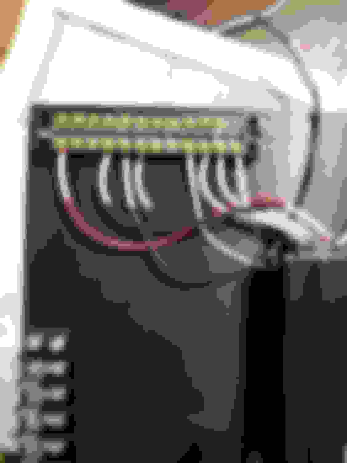
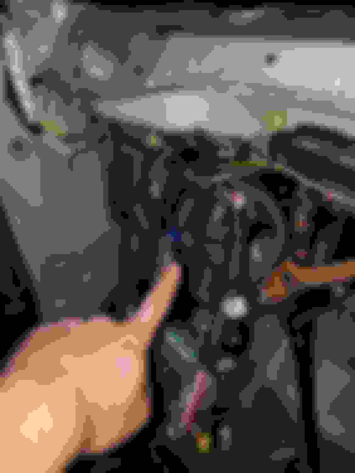
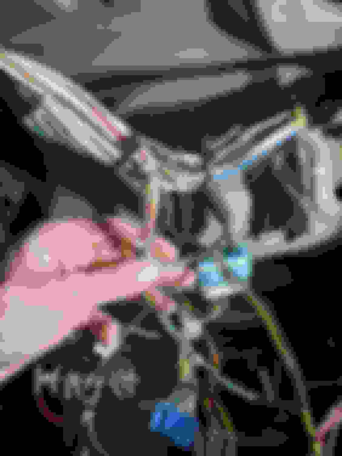
So above I show the wiring harnesses slapped together for the oil pressure, oil temperature, flex sensor, and the boost solenoid. I haven't installed the boost solenoid yet but the others are shown above. I chose to use a firewall location higher and close to my ECU to bring in the flex wiring. I will most likely use that for the boost solenoid routing as well. I havent planned on how I want to mount it yet.
Connector D for the aemv2 has been populated and 90% of the wires have been landed. I have a handful of things to continue which includes the inside harness and ap1 cluster wiring. So that's why I yanked the dash again.
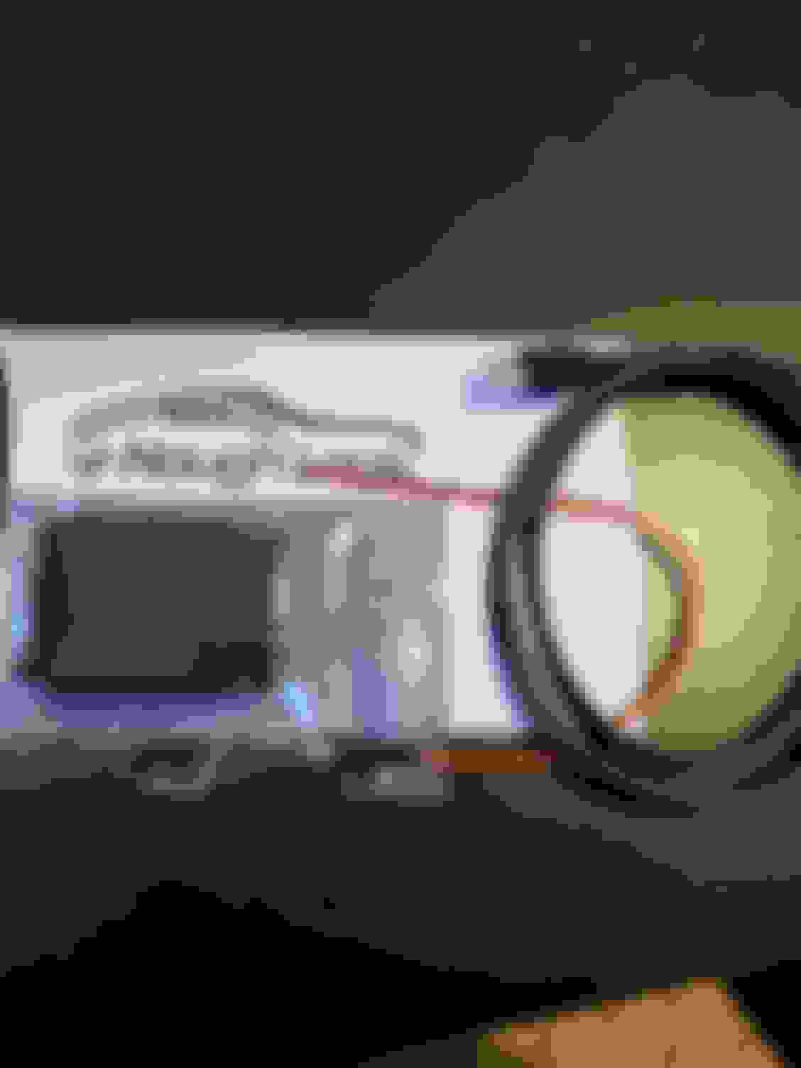
Finally got my hands on the E-nough logic transmitter to send my parameters to display on my iPad!
I completed my ap1 dash wiring but wont show pictures because it's not pretty lol. It will work but I started it years back and the way I went about it wasnt the best. Of course I'll have to test it all out when the car is running but the main wires are run.
I've got loads of pictures, diagrams, notes, and drawings to eventually post up on the inside harness. Ultimately I had to build an inside harness to tie in the ecu/engine harness to the chassis wiring to start the car traditionally. (No race car panel switches). So this is what aftermarket companies provide for k swapped cars. I'm still in the process of shaking down the wiring system but I'm confident that I'm almost finished. Wiring is built to interact with the civics main relay which provides power to key components. I will eventually post up all of this information once I've clarified its correct. To my knowledge that information is no where on the net... so I'll be providing information on the wiring for anyone who decides to do a f2k swap at home. Sure you can always pay a shop or company to build you harnesses but that's not my preference.
So I wrapped up a lot of electrical work this weekend and got the dash back in the car. I had the dash out to finalize integrating the engine harness into the chassis. All connections on the s2k harness that need integrated to the civic wiring are located in the c101 blue connector and connector A. Wiring from those s2k connectors are spliced into the grey civic c101 connector which is brought in from the engine bay on the driver side and the civic c131 connector which is the green connector on the passenger side kick board area.
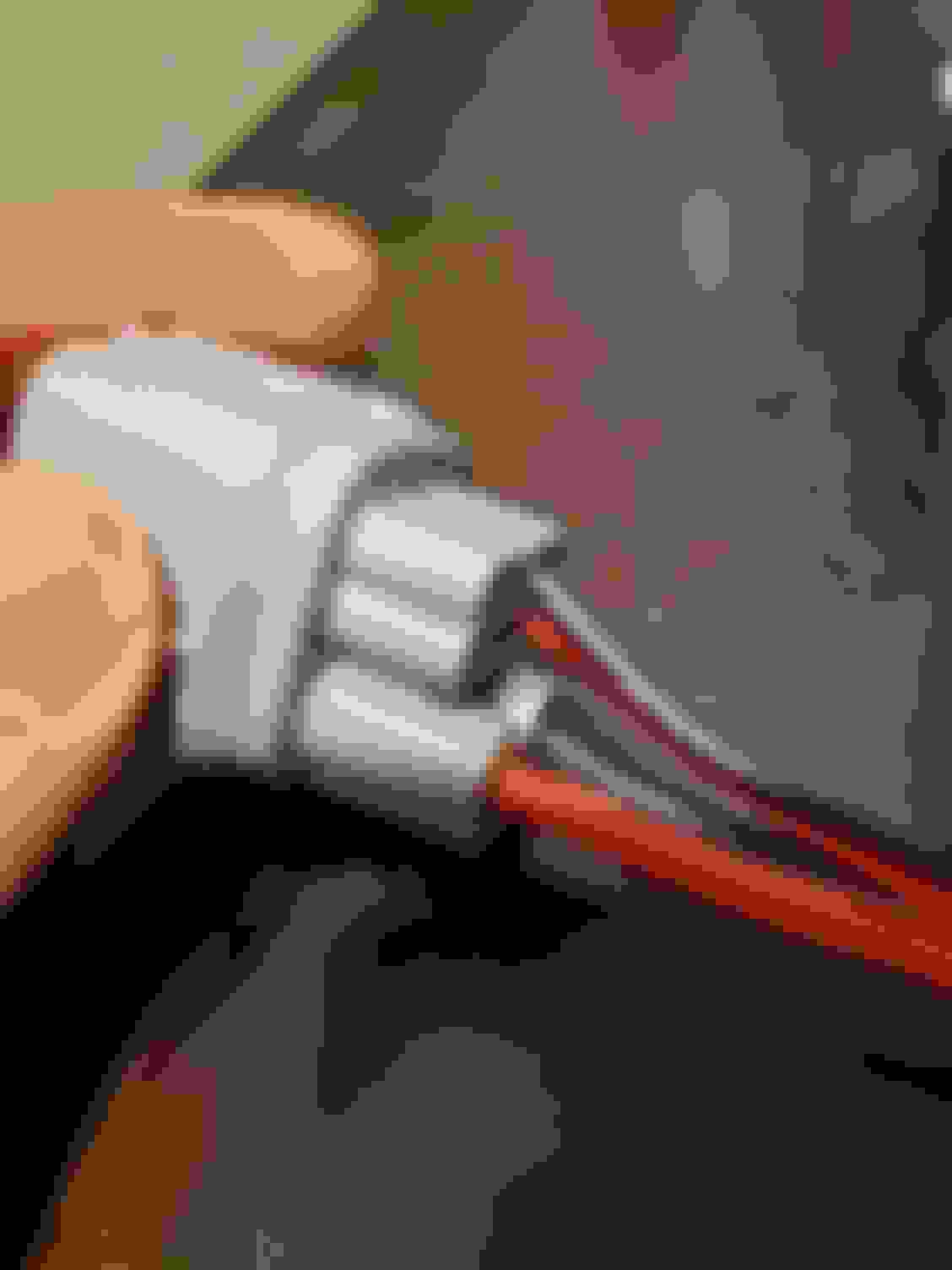
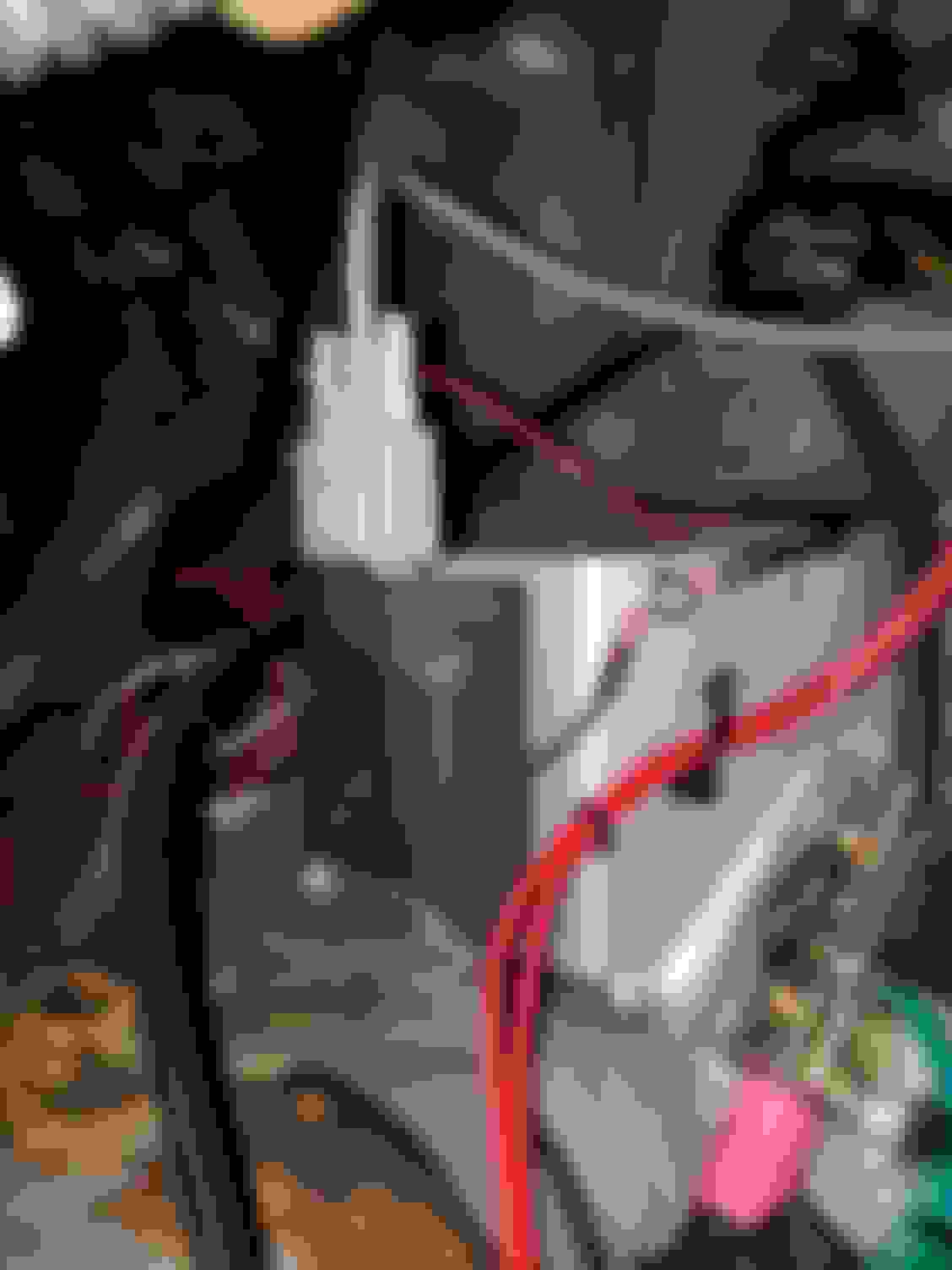
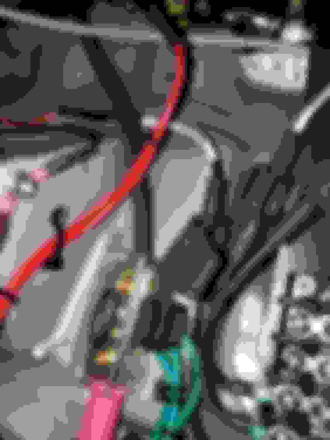
I purchased the Male side civic c101 connector to build a mini inside harness and ran it under the dash. This connector houses the wires for the main relay and starter.
C131 ties in a handful of wires from the A connector on the s2k side like the fuel pump grnd signal(pin A15), starter switch, ELD, etc. I'll eventually post diagrams and documentation of everything when I get around to it.
I also wired in a manual switch to activate the fuel pump for draining the tank (I dont have a drain on my refurbd tank). This is just a manual 12v supply to the fuel pump relay coils.
So HUGE milestone for me was reached yesterday. I was able to connect to the AEMv2 ! So I successfully populated power from the civic OEM power sources!
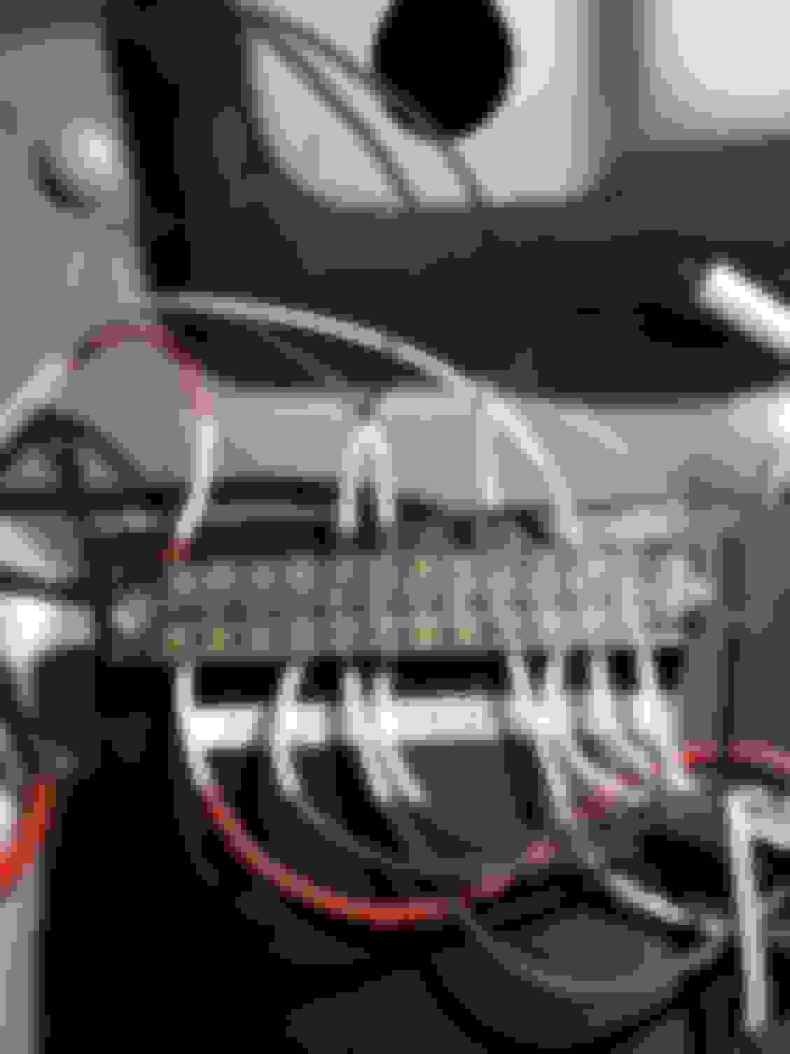
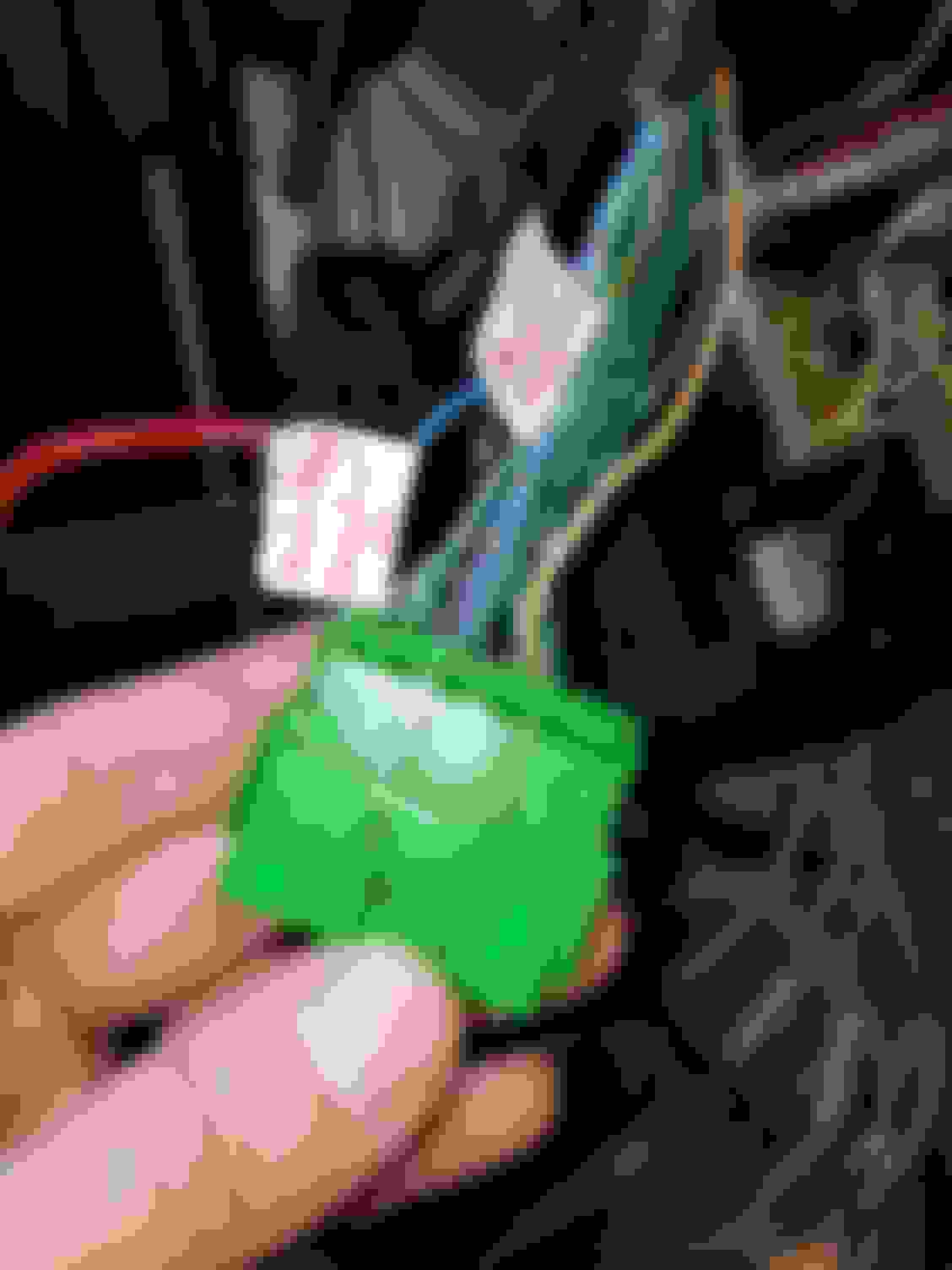
Below shows some connectors I purchased from Amazon to use on my c101, c131, and connector A wiring that ties in the engine/trans with the civic wiring. Reverse lights, ELD, VBU, brake switch, Fuel pump signal, and starter switch. Unfortunately I ran out of shrink wrap to finish the pin side of the connector which will be from the civic c131 connector.
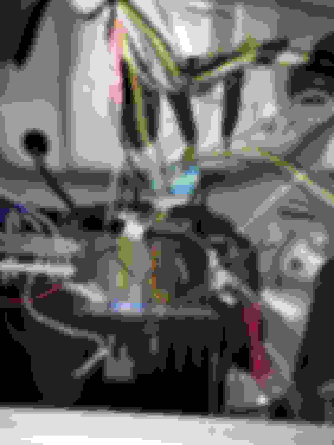
The other wiring shown is a handful of wires that go from connector A and C101 for the cluster. Those wires needed extended so they could reach the ECU. Lastly I show where I mounted the E-nough Logic transmitter and where ground and power are fed from.
Reverse lights are working. The s2000 connector needs swapped to the appropriate connector for the z3 trans. Very simple just remove the pins from the s2000 connector and switch over to the z3 connector. Polarity doesnt matter. I've also been working on another engine harness in parallel with all of the inside vehicle wiring. I just have to extend a few sensors and add my injector clips and it will be finished.
As for the mechanical side of things I have another intercooler ready to install and I purchased another set of tial 38mm MVS's.
I'm working on installing a dedicated welding circuit in my garage and I purchased a TIG welder for personal use. So in the near future I'll be fabricating a handful of things to include exhaust piping, waste gate dumps, intercooler mounts, and eventually intercooler piping.
Its been a bit since I've updated. Things have been up and down so I'll upload some progress first.
Pictures below are continuation of the final electrical tasks. The Enough logic transmitter is online and all internal wiring is complete. I will edit this post at a later date to publish a pinout for wiring this swap.
Finally I redid my wiring harness shown in the last photo. I kept it super simple and only extended a few wires while keeping the OEM distribution blocks.
As the car sits; all electrical is complete and acts accordingly to OEM ignition key turns. Fuel pump primes and 12v source is sent accordinly. There is a basemap loaded on the car and it is very close to starting...
I had to relocate the hazard switch to have operating turn signals so I modified the switch into a location near the driver side. Interior is a mess but it's mostly back together with what plastics I had left. Next I started adding some heat protection to my wiring, oil lines, and shift cables using fiberglass insulation wrap. I also started populating vacuum lines to the recirc valve, fpr, and dampner.
I grabbed a cheaper turbo blanket to try. I had to stretch it and wrap it differently to fit the turbo support but it should be okay. Using some aluminum stock, I fabbed up a quick little mount for the MAC solenoid. I used a rivet nut again for mounting. Slowly I've been purchasing the random fittings needed for vacuum and such. The last two photos above show the set of hood dampners I installed. They help a lot and are pretty stout.
So currently where I sit moving forward is with exhaust work.....
Currently where I sit moving backwards, is with a poorly built radiator.... I wont say anything further but as of right now I'm trying to fix this to use. Luckily I now have the tools to tig weld anything I want at home in my tiny garage.
Like I mentioned before I was running a few electrical circuits in my garage to accommodate my tinkering. I ran a few circuits for normal outlets but I also ran a dedicated welding circuit that will allow me to weld whatever I want. I finally received my tig welder and havent had a lot of time to fire up the torch. This update is the most recent with the modifications for exhaust routing. I also purchased a horizontal bandsaw that I've been dialing in for cutting the stainless.
Ps. Shout out to friends who help you better your skillset. A buddy of mine showed me a lot with the tig machine and it's greatly appreciated.
 02-08-2019, 03:30 PM