
Another S2K race car project


Thread Starter
Registered User
Joined: Nov 2011
Posts: 28
Likes: 0
1st I want to thank this forum and all who posted for wealth of knowledge and experience with this fine little car. This forum is an absolute jam.
2nd I want to apologize for my English.
It happened that a friend (Alexander) wanted an inexpensive car to compete in Russian time attack series. At this point I decided to stop working for teams and open my own race preparation/design/development shop. I had a bit of experience - raced myself for a couple of seasons in Russian touring car champ starting in 2001 while working as race driving instructor than worked as daq engineer, race engineer, tech. director and ceo in pro racing teams. Mostly formula cars but I had some involvement with GT’s, touring and LMP’s.
At the same point I was offered to become head of race car laboratory in Moscow MAMI university (which didn't actually exist and needs to be build from scratch), so all this combined led to yet another S2000 build.
I thought that sharing some aspects of design/build process may be useful for someone. I will try to share as much information as I possibly can without giving up real trade secrets.
We didn’t want anything really special because there was very little budget to operate with. So we decided not to aim at unlimited class (where Mitsu and Scoobs are dominating) but start with much more humble touring class that was still technically wide open.
Next season as Alexander grows as a driver we can opt for higher power and see what we can do in unlimited class but time will tell and we better take it step by step.
He had some offers – different cars but S2K was an easy choice within funds he allocated.
We started with establishing initial goals:
Overall concept:
Chassis
1. Some weight reduction - without going all out into 2000$ + per Lb territory.
2. Fully seam welded chassis.
3. Roll cage that will not only protect the driver but give adequate torsional stiffness.
Engine:
1 We go NA for several reasons - this car has a great little engine (if a little small in capacity and heavy in mass) and keeping it “as is” adds to purity. Nothing beats NA throttle response. Turbo’s add weight, bulk, heat, huge fuel pumps, intercoolers, compromises water heat exchanger packaging while increasing thermal load, complicates packaging, adds reliability issues to solve etc., etc… It also gives tons of power and torque. But Alexander said that for his first year he doesn’t need big power but will rather concentrate on his driving skills. For 2013 season we might go for more power but still it will remain NA.
2 We decided that ITB’s is the way to go for several reasons - throttle response, mid range (area under the curve always beats top end hp)
3 Stand alone ECU to control it properly.
Suspension (We both wanted this car to handle nicely, but it seems that Alexander didn’t anticipate how far it could go):
1. Fully rose jointed suspension so we can get it to handle as precise as possible.
2. I will take a look at OEM suspension points at target ride height and expected suspension movements. This will allow to setup the car consciously - using data acquisition and simulation tools to get high degree of understanding what car is doing on every point on the track (resultant wheel positions, ride heights, anti and jacking forces and ultimately individual wheel loads). It would also allow to decide if any modifications would be needed.
3. Two way adjustable shocks to save money and track time. Ohlins or Penske due to close relationships with both (build to my spec, size and valving) – was yet to decide.
4. 5 pairs of springs to have wide setup window (will explain reasons later)
5. A couple of different ARB’s (anti roll bar here and after) for front and rear (for same reasons as above)
6. Adjustable antis front and rear (“geometric” forces acting directly through suspension links) .
7. Further enhancements like friction reduction, 4 way shocks etc. should for next season AFTER driver is actually able to drive the car on its limit.
Basic data acquisition:
Most of vital functions (engine water and oil temp, pressures, rpm, gearbox temp, diff temp etc.)
Necessary channels for car/driver development (wheel speeds, rpm, steering pos., throttle pos, brake line pressures, accelerations)
Only limited car channels (suspension pots) as there’s no other reasonable way to learn the car and set it up. But sadly no load cells, no lasers, tire temps and other fancy stuff. So less to worry about.
Brakes:
Something tiny – time attack car normally works in short (4-5 laps) sessions and there’s literally no power so we don’t need to store huge amounts of thermal energy. We can go larger for 2013 if we require so.
Decided to go with AP racing 5000 pro calipers (4 pots, 152mm centers front), (4 pots, 130mm centers rear) and 330/295 rotors front/rear. This is not really pro solution but for the price they would do plus sizewise it’s typical configuration on WTCC touring cars which weight around 1100kg and have relatively similar power and tires
Dual master cylinders and separate front/rear brake line circuits so we can tune brake balance properly.
Transmission:
Class rules forbid dog engagement box so leave it for next season.
Car already had JS racing LSD (it looked to me like gliken – lots of friction pairs, low preload, ramp angles arranged so diff is relatively open under coast and moderately aggressive angle on the power side ) – I didn’t like it and would better go for Drexler (as I had nice relationships and experience with, and they could do it to my spec). This configuration of clutch type lsd may lead to mid corner and power US (understeer here and after) due to excessive amount of friction pairs but may be this car needs it – only testing will show.
Previous owner ordered assembled diff from Japan. When we took it apart for inspection we found that Pinion once touched LSD housing. Slightly but enough to leave several dents on the housing. It seems that bearing wasn’t tied to correct torque so (best guess) in reverse gear he might drop the clutch and get on gas in anger - so pinion was pulled rearwards and collided with housing. It had 4.3 final drive. Inspection show that this ring/pinion should still work and no serious damage. It also doesn’t show overheating signes. 4.3 is way too “long” for local tracks and I would go for 4.8 or 5.1 but that’s not cheap. So due to budget considerations we decided to keep it as is, not add cooling but to keep a close eye on it. Only mod is installing temp sensor. Initial testing will show if current setup is adequate and if not we’ll see what we can do.
I suggested tilton clutch/flywheel package but Alexander moved it to next season plans.
Aero:
There’s no budget for proper aero study (which would involve initial aero mapping in the WT and using straight line testing, 3d scanning entire car, produce water tide surface CAD model from raw scan points cloud, produce high quality CFD grid containing at list 60-80 billions of cells. Work on simulation until it correlates well with tunnel/straight line testing data. Than design required updates, again produce CFD grid, set up CFD study with required optimization parameters. If enough computing and man power than mapping full range of pitch, heave, roll, yaw within predicted operational window. Than validate it in WT and straight line, again do ride height mapping, etc., etc – in fact it’s an endless process) so decided to design aero bits based on previous experience. If lots of data is available regarding which designs work and how they do it, which angles are safe, what to do to avoid flow separation, if there’s solid understanding of main flow features around car body than it’s possible to arrive at up to 55-70% of potential downforce.
Decided that car should have fully closed floor with front and rear diffusers. Full span rear wing. We should have access to straight line testing and may be some WT time (thanks to MAMI university) and if it happens it will enable us to optimize rear wing location so it interacts properly with floor and for best available downforce to drag ratio. We’ll plan full aero mapping so we can use it in setup process when testing starts.
Next stage we may add various smaller aero bits – front vanes, vortex generators, louvers, gurneys etc and work on details to help optimize overall package and add tunability. We aim for later addition of higher engine power so initially it might be too draggy for current motor but we’ll see. There’s no budget for separate low/medium/high downforce packages so we’ll design something in the region of medium and hope for more ponys later on.
Overall target for aero is to be effective enough to justify weight and budget penalty it brings along.
Cooling:
We decided to go with conventional tilted front radiator with ducts leading the air flow from bamper opening to heat exchanger and from heat exchanger out through bonnet. This layout is decades old but still very effective for front engine cars and should aid cooling, CGH and reduce front lift.
With oil experience suggests oil/water instead of oil/air so we go with Laminova heat exchanger – always worked fine in various cars. We might think and use combined heat exchanger with separate circuits for engine oil and gearbox oil.
OK, time to get to work – first step is learning what we have as a base. And there will be less words and a bit more images hopefully.
Thread Starter
Registered User
Joined: Nov 2011
Posts: 28
Likes: 0
Car arrived in the shop. It was a nice little car that competed in touring class time attack series and finishing 1 and 2nd usually in last couple of seasons.


Bolt on roll cage had to go. It simply is not safe enough.

Got the car on setup platen and had a good look at it.


Became interested about what ‘s inside of it we started taking it apart.


Pile of parts started to grow.

Than we started taking all the sealant off the chassis and prepare it to seam welding. Than we welded every little seam in the chassis. Some where continuous welds done in the way to avoid heating the metal excessively (one welds 0.75” stitch, than 5” gap and another stitch, gap, stitch etc. Than go on the other side to let this side cool. Than when it cooled come back and add more stitches till it becomes continuous line). This was done in most stressed areas. Less critical areas where done in conventional stitch/gap way.
I sure made pictures but can’t find it at the moment. Hope will add them a bit later.
Bolt on roll cage had to go. It simply is not safe enough.
Got the car on setup platen and had a good look at it.
Became interested about what ‘s inside of it we started taking it apart.
Pile of parts started to grow.
Than we started taking all the sealant off the chassis and prepare it to seam welding. Than we welded every little seam in the chassis. Some where continuous welds done in the way to avoid heating the metal excessively (one welds 0.75” stitch, than 5” gap and another stitch, gap, stitch etc. Than go on the other side to let this side cool. Than when it cooled come back and add more stitches till it becomes continuous line). This was done in most stressed areas. Less critical areas where done in conventional stitch/gap way.
I sure made pictures but can’t find it at the moment. Hope will add them a bit later.

Thread Starter
Registered User
Joined: Nov 2011
Posts: 28
Likes: 0
Thanks murderedrsx 
We scanned the car to get it into CAD and to be able to start design work.
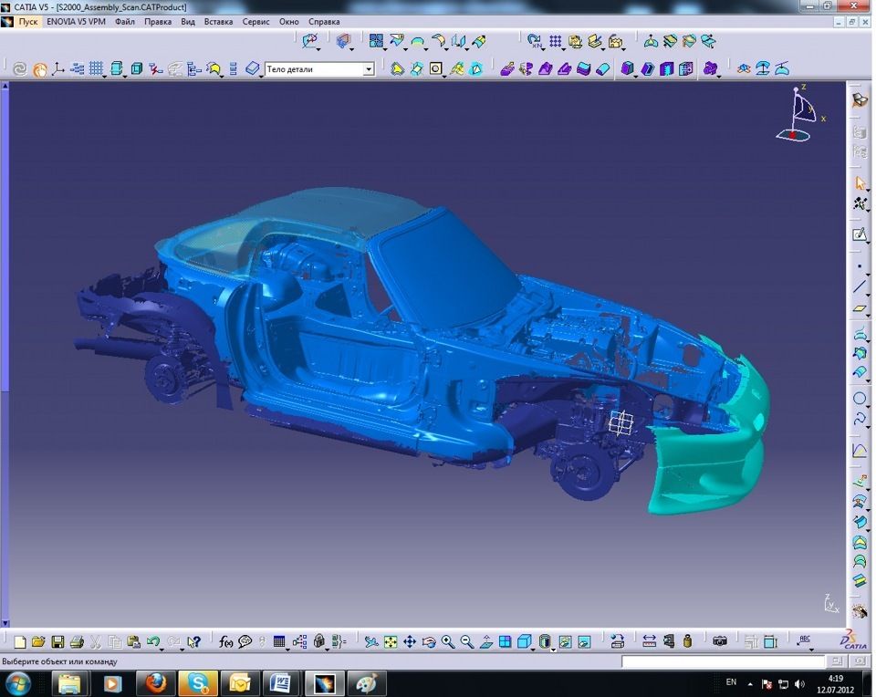
Than we thoroughly located and recorded 3d coordinates of existing suspension points. I have to say that what we’ve got is not truly standard S2000 suspension points but rather what was present. Previous owner added various JS bits, bump steer kit etc.
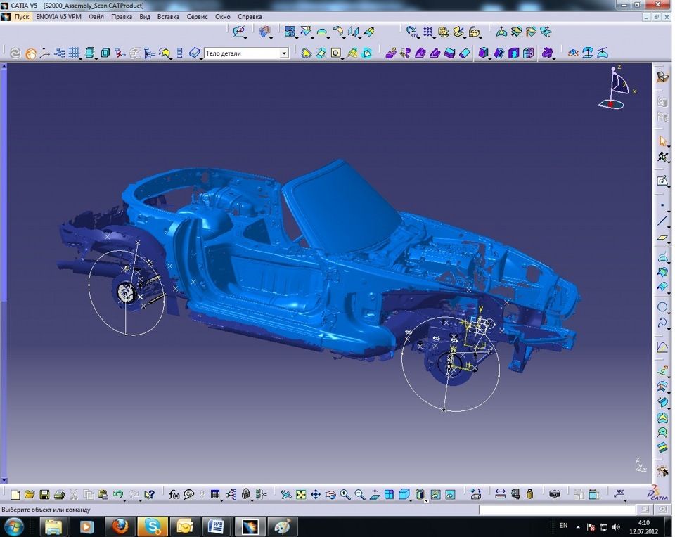
Anyway it enabled to build suspension model and start studying what and how it does.
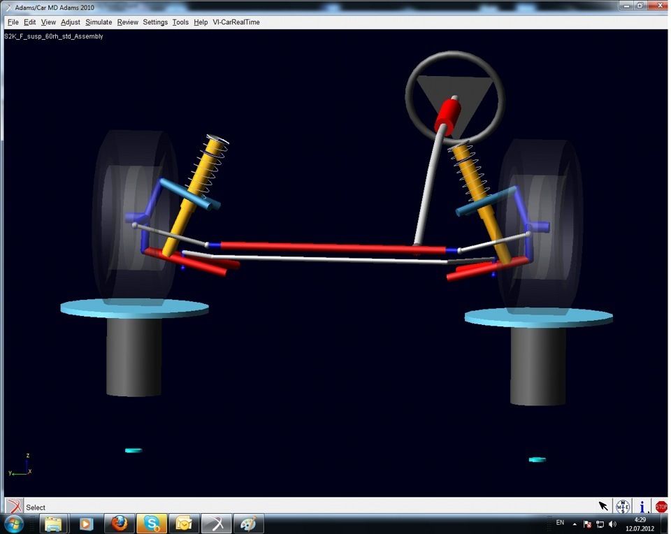
Front suspension ADAMS/Car model at 60mm ride height
Rear suspension
We scanned the car to get it into CAD and to be able to start design work.

Than we thoroughly located and recorded 3d coordinates of existing suspension points. I have to say that what we’ve got is not truly standard S2000 suspension points but rather what was present. Previous owner added various JS bits, bump steer kit etc.

Anyway it enabled to build suspension model and start studying what and how it does.
Front suspension ADAMS/Car model at 60mm ride height

Rear suspension

 x2.
x2. 
Trending Topics
Thread Starter
Registered User
Joined: Nov 2011
Posts: 28
Likes: 0
OK, time to look at suspension how and what it does. If one is interested in loads at every suspension member/joint, vibrations etc one will look at ADAMS/Car (270k + 50k euro yearly piece of software) and we did just that:
One of countless analyses is simulating cornering loads on front axle – applying and ramping up cornering forces and contact patch normal forces + steering from static and up (inside tire loose normal force and generate less cornering force and outside tire gain normal force and increase cornering force)
If I learn how to add YouTube video I’ll insert it here.
For now here’s a couple of images of analyzing results:
Some of the plots one might look at (superimposed one over the other)

Here’s roll center height vs roll angle – many will look at it closely and design their suspension geometry around it. It’s actually futile because roll center (even force based roll center as A/Car calculates it) is only a result and not the cause of anything. However by looking at how quiet/noisy it is one may get some useful info about suspension characteristics.

But here’s what is causal – front view swing arm angle. This is what determines wheel loads and forces acting on chassis due to suspension geometry (so called geometric part of weight transfer or jacking forces)
In other words suspension designer really cares about what IC’s (instant center here and after)are doing – especially its height.

One of countless analyses is simulating cornering loads on front axle – applying and ramping up cornering forces and contact patch normal forces + steering from static and up (inside tire loose normal force and generate less cornering force and outside tire gain normal force and increase cornering force)
If I learn how to add YouTube video I’ll insert it here.
For now here’s a couple of images of analyzing results:
Some of the plots one might look at (superimposed one over the other)
Here’s roll center height vs roll angle – many will look at it closely and design their suspension geometry around it. It’s actually futile because roll center (even force based roll center as A/Car calculates it) is only a result and not the cause of anything. However by looking at how quiet/noisy it is one may get some useful info about suspension characteristics.
But here’s what is causal – front view swing arm angle. This is what determines wheel loads and forces acting on chassis due to suspension geometry (so called geometric part of weight transfer or jacking forces)
In other words suspension designer really cares about what IC’s (instant center here and after)are doing – especially its height.
Thread Starter
Registered User
Joined: Nov 2011
Posts: 28
Likes: 0
In case of S2000 we see lots of PRO roll. This easily explains why many race prepped S2000s react really well to big front ARB’s (an impression I picked reading this forum) And the closer one gets his car to the ground the lower it’s roll resistance.
1. Darn! This is actually a big problem… Having instant centers too low basically reduce roll resistance and if it’s a lot lower than 0 than actually large force is acting directly through suspension links lifting outside of chassis and lowering inside – pro roll it is called for a reason. Roll is always a problem as you generally loose camber (which many say is the name of the game) and your aero platform is moving unfavorably.
First big thing to think about. (reminder – we’re talking about semi standard suspension at 60mm ride height)
I have to add here that wheels with its ET where not factory spec and front axle actually had negative scrub radius . Which leads to more problems with steering feel and more seriously to structural problem. Combined with relatively large anti dive when car brakes hard than generated torque will try to pull upper a –arms out of the car. After noticing this I wanted to look at Fr UCA (front upper control arm here and after) mounts on chassis side but mechanic was first asking me to come and look “this thing is already ripped away half way” he declared and smiled. It looked like another 10 – 15 decelerations (generating around 1 – 1.2g as ex - owner may be did) and UCA rear leg might brake away. Roughly 50% of rear upper mounting was hanging in the air. It reminded me that this was sort of common failure mode and some tuners sell reinforcements. It’s used on Andrew’s car (great unlimited class build thread that I learned from on this forum).
2nd big thing to think about.
While ripping things off car down to bare body we weighted each component at the start but moving into new place (race car lab in MAMI) and finding that it actually doesn’t exist and there’s no place for the shop added a bit of a hussle. Moved in local FSAE shop alongside their current single seater build (till place for shop is found within university. I helped FSAE team along with some suggestions and I might post some images if anyone is interested. They build a nice little car and it is much stiffer torsinally and in bending while lighter and has many other advantages over previous season design.
`
So it happened that along the move list of component weights was lost and its electronic form was lost as well. We reweighted most of the components again but lots of bits of metal that we cut away and lots of sealant that was cleaned off - I don’t know how much it weighted. Feel sorry about it.
Anyway – I looked at steering rack at wooping 24 kg (52.8 lbs) it seemed like a easy chunk of weight. I looked at front subframe and it seemed weak in torsion while bulky. Also it’s connection to chassis was prone to movement – i.e. it could easily change its position under load and as a result change alignment etc. significantly. All cars have differences in their setup and setdown sheets (list of settings before outing and right after pit in) but one would want to keep it minimal. Subframe was another 20 + kg (44+ lbs) – I don’t have the list handy atm but as I remember even heavier than that.

Looked at arms (lower arm with ball joint 5,8kg, UCA 1.9kg). It all seem too heavy and a bit weak at the same time…
3d big thing to think about.
Same story with rear suspension. There was JS racing rear subframe. There where some seam welds and gussets added. But overall it remained weak in torsion as it was made of 4 corner shapes which is inherently soft/weak. Here’s a hint – good structure even if its joints are pin connections (not welds which restrict all movement) which keep free rotational degree of freedom it would not move. 4 corner shape will move if pinned. Triangle will not move and it is inherently stiff. If I remember it right rear subframe was another 35kg (77lbs). A - Arms again heavy and weak (closed filled section casting will always loose in stiffness per lbs to closed empty section i.e. tube has always higher stiffness to weight ratio than bar). We have to remember that it's normal for mass production cars - manufacturers got to keep the costs down.

Another big thing to think about.
Looking at rear geometry it was evident that IC’s are a bit too high, a bit too much anti squat to my liking and it seems that IC’s are moving a bit too much.
More things to think about.
Next stage is to look at handling part of existing geometry characteristics. ADAMS/Car is great and very in-depth but it is also very cambersome and extremely user unfriendly ad slow to operate. For handling characteristics I don’t know anything better than WinGeo software written by Bill Mitchell.
1. Darn! This is actually a big problem… Having instant centers too low basically reduce roll resistance and if it’s a lot lower than 0 than actually large force is acting directly through suspension links lifting outside of chassis and lowering inside – pro roll it is called for a reason. Roll is always a problem as you generally loose camber (which many say is the name of the game) and your aero platform is moving unfavorably.
First big thing to think about. (reminder – we’re talking about semi standard suspension at 60mm ride height)
I have to add here that wheels with its ET where not factory spec and front axle actually had negative scrub radius . Which leads to more problems with steering feel and more seriously to structural problem. Combined with relatively large anti dive when car brakes hard than generated torque will try to pull upper a –arms out of the car. After noticing this I wanted to look at Fr UCA (front upper control arm here and after) mounts on chassis side but mechanic was first asking me to come and look “this thing is already ripped away half way” he declared and smiled. It looked like another 10 – 15 decelerations (generating around 1 – 1.2g as ex - owner may be did) and UCA rear leg might brake away. Roughly 50% of rear upper mounting was hanging in the air. It reminded me that this was sort of common failure mode and some tuners sell reinforcements. It’s used on Andrew’s car (great unlimited class build thread that I learned from on this forum).
2nd big thing to think about.
While ripping things off car down to bare body we weighted each component at the start but moving into new place (race car lab in MAMI) and finding that it actually doesn’t exist and there’s no place for the shop added a bit of a hussle. Moved in local FSAE shop alongside their current single seater build (till place for shop is found within university. I helped FSAE team along with some suggestions and I might post some images if anyone is interested. They build a nice little car and it is much stiffer torsinally and in bending while lighter and has many other advantages over previous season design.
`
So it happened that along the move list of component weights was lost and its electronic form was lost as well. We reweighted most of the components again but lots of bits of metal that we cut away and lots of sealant that was cleaned off - I don’t know how much it weighted. Feel sorry about it.
Anyway – I looked at steering rack at wooping 24 kg (52.8 lbs) it seemed like a easy chunk of weight. I looked at front subframe and it seemed weak in torsion while bulky. Also it’s connection to chassis was prone to movement – i.e. it could easily change its position under load and as a result change alignment etc. significantly. All cars have differences in their setup and setdown sheets (list of settings before outing and right after pit in) but one would want to keep it minimal. Subframe was another 20 + kg (44+ lbs) – I don’t have the list handy atm but as I remember even heavier than that.
Looked at arms (lower arm with ball joint 5,8kg, UCA 1.9kg). It all seem too heavy and a bit weak at the same time…
3d big thing to think about.
Same story with rear suspension. There was JS racing rear subframe. There where some seam welds and gussets added. But overall it remained weak in torsion as it was made of 4 corner shapes which is inherently soft/weak. Here’s a hint – good structure even if its joints are pin connections (not welds which restrict all movement) which keep free rotational degree of freedom it would not move. 4 corner shape will move if pinned. Triangle will not move and it is inherently stiff. If I remember it right rear subframe was another 35kg (77lbs). A - Arms again heavy and weak (closed filled section casting will always loose in stiffness per lbs to closed empty section i.e. tube has always higher stiffness to weight ratio than bar). We have to remember that it's normal for mass production cars - manufacturers got to keep the costs down.
Another big thing to think about.
Looking at rear geometry it was evident that IC’s are a bit too high, a bit too much anti squat to my liking and it seems that IC’s are moving a bit too much.
More things to think about.
Next stage is to look at handling part of existing geometry characteristics. ADAMS/Car is great and very in-depth but it is also very cambersome and extremely user unfriendly ad slow to operate. For handling characteristics I don’t know anything better than WinGeo software written by Bill Mitchell.


