
Dealing with the "crappy tune zone"


Joined: Mar 2010
Posts: 4,742
Likes: 211
Very interesting thread, as always Gernby! 
First question I'd love to know is how much better is your gas mileage now over your previously tuned configuration..? Not to oversimplify your solution, but basically you force the hondata to open the throttle plate to 100% for the "crappy tune" zones? (crappy tune zone being the rpm range where MAP is at 100% but the throttle plate opening is <100% hurting gas mileage?) I'll reread your posts again, but you're then "tuning" the throttle map to give more resolution to the areas <100% of the throttle plate opening?
Nice work! I've been sidetracked with other things, but definitely makes me want to hook up my hondata and drive around for some datalogging.

Thread Starter
Former Sponsor
Joined: Mar 2002
Posts: 15,526
Likes: 19
I eventually went back to a stock equivalent, and retuned from there. This seems to be the perfect fuel tune for my car and altitude. When I look at a datalog of my commute to work (12 miles of mixed driving in traffic and surface streets with stop lights), I get very few spikes in AF (asside from overrun). I was surprised to find that the high cam fuel was more complicated than the low cam fuel. I thought it would have been the other way around.


Thread Starter
Former Sponsor
Joined: Mar 2002
Posts: 15,526
Likes: 19
Very interesting thread, as always Gernby!
First question I'd love to know is how much better is your gas mileage now over your previously tuned configuration..? Not to oversimplify your solution, but basically you force the hondata to open the throttle plate to 100% for the "crappy tune" zones? (crappy tune zone being the rpm range where MAP is at 100% but the throttle plate opening is <100% hurting gas mileage?) I'll reread your posts again, but you're then "tuning" the throttle map to give more resolution to the areas <100% of the throttle plate opening?
Nice work! I've been sidetracked with other things, but definitely makes me want to hook up my hondata and drive around for some datalogging.
Thanks. I haven't done enough of a "controlled" test for MPG, since I've continued to do so many tuning pulls each day. However, with my previous (typical) calibrations, I would not reach 200 miles on a tank of gas, unless I did an extended drive on the highway. I've also NEVER reached 300 miles on a tank even when I was doing all highway. But I have been exceeding 200 miles with every tank since I started this thread, and I did hit 300 miles for the first time ever on a single tank last week with MIXED driving. That was mostly highway, with probably 60 miles of surface street driving. I couldn't believei t, since I was still driving in my usual manner (aggressively).
Thread Starter
Former Sponsor
Joined: Mar 2002
Posts: 15,526
Likes: 19
I put my stock intake back in, and did a full retune. I was surprised to see that the stock box doesn't really generate much of a resonance, so it wouldn't create as signficant of an issue in the "crap zone". Of course, that really isn't great news, since it is also noticeably slower. When I started driving it, the car felt just like it did with the restricted throttle plate. The pedal really has a dead feal to it, even with the throttle map I posted about above.
Below are the new throttle maps for the stock intake...


Below are the new throttle maps for the stock intake...

Registered User
Joined: Jan 2009
Posts: 1,064
Likes: 1
The only things I would add / change about what you said are:
1) I wouldn't call it "suffers from excessive resonance", since that resonance causes significant performance increases. We like resonance!
2) When the throttle plate is open just enough to achieve full load, it isn't the slight restriction or turbulance in the intake air that is preventing resonance. It is the reflection of the pressure waves (negative pressure waves from the intake valves that bounce off the back side of the throtlte plate, and positive pressure waves, or rarefraction waves, from the air filter inlet bouncing off the front side of the throttle plate). When the throttle plate is fully open, those pressure waves travel freely up and down the intake plenum, which gives a "super charge" of the intake air in certain RPM ranges.
3) The reason why my throttle map doesn't look like the one you suggested is because I don't like the 1:1.5 pedal to plate ratio of the stock map. I wanted to maintain true part throttle / reduced load for the bottom ~60% of the throttle pedal across all RPMs.
From talking with my friend, the best resonance that occurs in the engine is the air bouncing off the valve just as it closes, spring boarding off the plenum air @ the speed of sound and hitting the valves again just as they are opening that causes the largest resonance hump. This all occurs inside the manifold. Now there is resonance from every component from intake to exhaust. But the ones with the biggest effects are on the intake side.
And where there is good resonance at one specific rpm range, there is bad resonance exactly double that rpm range later. So you must be careful with your designs.
Thread Starter
Former Sponsor
Joined: Mar 2002
Posts: 15,526
Likes: 19
From talking with my friend, the best resonance that occurs in the engine is the air bouncing off the valve just as it closes, spring boarding off the plenum air @ the speed of sound and hitting the valves again just as they are opening that causes the largest resonance hump. This all occurs inside the manifold. Now there is resonance from every component from intake to exhaust. But the ones with the biggest effects are on the intake side.
And where there is good resonance at one specific rpm range, there is bad resonance exactly double that rpm range later. So you must be careful with your designs.
And where there is good resonance at one specific rpm range, there is bad resonance exactly double that rpm range later. So you must be careful with your designs.
Another interesting fact is that these pressure waves also have an impact on the MAP sensor reading. The net effect is that your MAP reading will read low at the RPMs where you are getting good resonance, and the MAP value will read high when you are getting bad resonance. This means that you really can't judge the flow of your setup by the MAP reading. A low MAP value doesn't necessarily mean that you have a restriction!
Registered User
Joined: Jan 2009
Posts: 1,064
Likes: 1
Yes, i never said anything different from what you were referring to. I agree with all that. To solve the pressure waves occurring in the exhaust this is why a lot of the custom headers have anti reversion chambers to limit the pressure waves bouncing back.
All i notice on my car is the map pressure reading very high when on the low cam and gradually decreasing to the rev limiter once i get into vtec. I don't really notice any resonance dips or peaks in MAP pressure, so i think the MAP sensor is much less affected by resonance than, say, a MAF sensor.
All i notice on my car is the map pressure reading very high when on the low cam and gradually decreasing to the rev limiter once i get into vtec. I don't really notice any resonance dips or peaks in MAP pressure, so i think the MAP sensor is much less affected by resonance than, say, a MAF sensor.
Thread Starter
Former Sponsor
Joined: Mar 2002
Posts: 15,526
Likes: 19
Yes, i never said anything different from what you were referring to. I agree with all that. To solve the pressure waves occurring in the exhaust this is why a lot of the custom headers have anti reversion chambers to limit the pressure waves bouncing back.
All i notice on my car is the map pressure reading very high when on the low cam and gradually decreasing to the rev limiter once i get into vtec. I don't really notice any resonance dips or peaks in MAP pressure, so i think the MAP sensor is much less affected by resonance than, say, a MAF sensor.
All i notice on my car is the map pressure reading very high when on the low cam and gradually decreasing to the rev limiter once i get into vtec. I don't really notice any resonance dips or peaks in MAP pressure, so i think the MAP sensor is much less affected by resonance than, say, a MAF sensor.
I haven't done any testing with MAF sensors, but I wouldn't expect it to be that different.
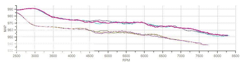
Below is a comparison of my MAP curve with my PWJDM intake compared to my stock intake. The stock intake shows a peak MAP value below 2500 RPMs, then quickly drops before 3K, but the PWJDM does the same about 600 RPMs later. The dips in MAP occur at the same location as the resonant humps in my fuel maps.
MAP curves:
PWJDM fuel map

Stock fuel map


Joined: Dec 2010
Posts: 637
Likes: 2
Greg, if im understanding you correctly are you dialing in the throttle plate DBW table to compensate by eliminating the "dead throttle plate range" THR% that exists between TPS% at zero VACUUM and 100% THR?
I'm not used to Hondata, but wouldn't the solution be to switch to Alpha-N mode if possible?
http://www.megamanual.com/v22manual/mtune.htm#alphan
Both models below accomplish the same thing - determining the correct fueling given engine sensor conditions. The top is used in the aem basemap for a MY00-05, and the bottom is a completely different model basemap used for 06+ #6053 EMS.
I recently changed my setup and the 'dead crappy tune zone' got bigger and my car ran like crap. More than one way to deal with it is to direct more density breakpoints to the crappy tune zone (to get finer control on low vacuum conditions to zero vacuum), but I decided to try a new approach and learn something.
The following is the standard Speed-Density Model (FUEL ONLY):
I highlighted 101KPA row since that is WOT, anything additional would be positive pressure aka BOOST which is not applicable to normal aspriated setup. The traditional speed density model doesn't use TPS to determine fuel at all except for DFCO (injectors off during decel), accel pump (thr tip in), determine idle state/ramp, *vtec trigger.

The following is hybrid Alpha-N Model aka TPS FUEL in AEMTuner (FUEL ONLY):

The rows are TPS% and the columns are engine speed RPM. The density/MAP is the 2d table on the bottom with 0% trim being 101kpa aka WOT.
As you can see in the Alpha-N model with MAP (boost) trim, the fuel table TPS ROW has a dead range approximately above of the cells that i highlighted. I believe those cells can still be tuned on a load bearing dyno rather than having to sacrifice between partial and WOT performance. The MY00 - MY05 owners don't have DBW tables and flashpros to compensate for that dead partial throttle range so they must be dealt with directly.
Since our ECU is based on manifold pressure (not throttle position), the ECU gives the same amount of fuel at 900 mBar no matter what the position of the throttle plate is. However, the "ideal" amount of fuel changes a LOT based on the position of the throttle plate! This is due to the huge impact that intake resonance has on ideal fuel without having much impact on manifold pressure.
http://www.megamanual.com/v22manual/mtune.htm#alphan
Using the speed-density algorithm, MAP is the main variable and VE is a 'tweak'. On alpha-N the VE table is the main variable, as TPS is used as a lookup into this table. Actually it is a fuel map rather than a VE table. One thing you have to always remember with alpha-N that you don't actually know where the effective WOT is anymore (i.e., when you have enough throttle that opening it further doesn't affect the amount of air being ingested). At low RPM WOT could be only 20% throttle.
I recently changed my setup and the 'dead crappy tune zone' got bigger and my car ran like crap. More than one way to deal with it is to direct more density breakpoints to the crappy tune zone (to get finer control on low vacuum conditions to zero vacuum), but I decided to try a new approach and learn something.
The following is the standard Speed-Density Model (FUEL ONLY):
I highlighted 101KPA row since that is WOT, anything additional would be positive pressure aka BOOST which is not applicable to normal aspriated setup. The traditional speed density model doesn't use TPS to determine fuel at all except for DFCO (injectors off during decel), accel pump (thr tip in), determine idle state/ramp, *vtec trigger.
The following is hybrid Alpha-N Model aka TPS FUEL in AEMTuner (FUEL ONLY):
The rows are TPS% and the columns are engine speed RPM. The density/MAP is the 2d table on the bottom with 0% trim being 101kpa aka WOT.
As you can see in the Alpha-N model with MAP (boost) trim, the fuel table TPS ROW has a dead range approximately above of the cells that i highlighted. I believe those cells can still be tuned on a load bearing dyno rather than having to sacrifice between partial and WOT performance. The MY00 - MY05 owners don't have DBW tables and flashpros to compensate for that dead partial throttle range so they must be dealt with directly.
Thread Starter
Former Sponsor
Joined: Mar 2002
Posts: 15,526
Likes: 19
I would not want to use an Alpha-N tuning model, since that would run rich or lean depending on changes in weather or altitude. I think the ideal tuning model would be to add fuel and timing compensation tables by RPM and TPS to the standard Speed Density tuning model.
The adjustments I made to the DBW throttle map were not an attempt to fix the tune as much as spending less time in the "crappy tune zone".
The adjustments I made to the DBW throttle map were not an attempt to fix the tune as much as spending less time in the "crappy tune zone".