
2005 turbo setup


Thread Starter


Joined: Sep 2009
Posts: 460
Likes: 90
Having some issues with the clutch possibly binding. Also forgot to take the thickness of the straight edge out when measuring the depth of the clutch disc spline. So my .14" gap dropped to 0 pretty much from the clutch disc to the cd009 throwout bearing guide. Since I'm basically combining 2 different kits it won't work out as is. I have a .50" thick adapter plate and I think this 850 clutch is based on maybe a ~.75" plate. Pressing the clutch would barely release the driveshaft.
The best option is to make a spacer and add it to the adapter plate. It will give clearance between the clutch disc and throwout guide, and will also move the discs more toward the center of the input shaft splines. I'll have to space the throwout bearing again....change up the transmission mount...and possibly change the shifter extension.
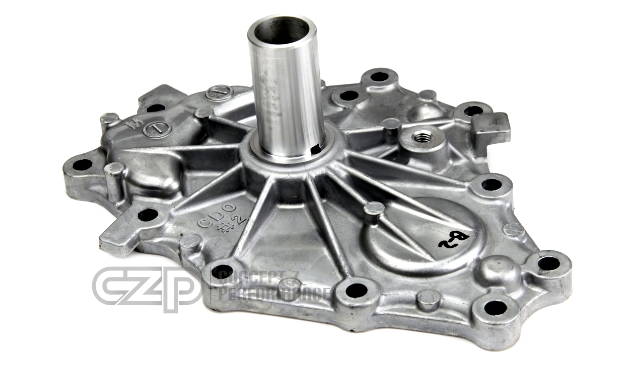
How it is now

After adding a .190" spacer

There is a small shiny ring on the bearing guide. I'm pretty sure this is from the clutch disc rubbing against it.

Here is where I screwed up my measurement.
.740" vs ~.6xx"


Throwout bearing movement.

I also shortened some honda bolts to use with the spacer.


The best option is to make a spacer and add it to the adapter plate. It will give clearance between the clutch disc and throwout guide, and will also move the discs more toward the center of the input shaft splines. I'll have to space the throwout bearing again....change up the transmission mount...and possibly change the shifter extension.
How it is now
After adding a .190" spacer
There is a small shiny ring on the bearing guide. I'm pretty sure this is from the clutch disc rubbing against it.
Here is where I screwed up my measurement.
.740" vs ~.6xx"
Throwout bearing movement.
I also shortened some honda bolts to use with the spacer.


Joined: Mar 2003
Posts: 6,507
Likes: 51
From: Sellersburg, IN
Hate to see that man. Looks like you have a bit of work to get that sorted out. Is there any way you could sink the throwout bearing further into the bellhousing by machining the bellhousing throwout bearing seat down a bit and getting things to work out that way or am I misunderstanding things?
Last edited by Spoolin; Aug 26, 2020 at 05:44 PM.
Thread Starter
Joined: Sep 2009
Posts: 460
Likes: 90
Hate to see that man. Looks like you have a bit of work to get that sorted out. Is there any way you could sink the throwout bearing further into the bellhousing by machining the bellhousing throwout bearing seat down a bit and getting things to work out that way or am I misunderstanding things?
Yeah it sucks. I should expect some hiccups as they are not from the same vendor.
The throwout bearing gap is good to the fingers of the clutch, but the bearing guide covering the input shaft isn't. I would have to shorten this "snout" down.
I can either:
-turn the splined section down on the clutch disc.
-cut the throwout bearing guide (snout) on the trans (kind of sounds like what you are saying)
-space the transmission away from the block
I like the idea of getting more spline engagement with the clutch discs (this only happens with the spacer), especially if the discs release toward the aft of the car (where spline engagement already seems short).
Thread Starter
Joined: Sep 2009
Posts: 460
Likes: 90
Got a small sheet of .190" aluminum in. There is probably some deflection in it, but I'm not too worried about it since it is just a spacer with through-holes. The transmission bolts will close the gaps out.
Just a simple trace with a sharpie to get a rough cut.


Rough-cut is done, now to locate the dowels so I can "lock" the pieces together. Once they are locked, I can locate the bolt holes as well as finish the cut with a flush-bit on a router.


I used the lathe to drill a hole through the center of a bolt. It took a couple tries/bolts to get a good center. But this will make it easier to start centered pilot holes to drill new holes into the spacer.


So far it lines up good enough.


Flush cutting the spacer to match the adapter plate. It'll cut the aluminum decent. You have to keep a good grip on the router and only cut in the correct direction. It becomes uncontrollable going the other way.


Just a simple trace with a sharpie to get a rough cut.
Rough-cut is done, now to locate the dowels so I can "lock" the pieces together. Once they are locked, I can locate the bolt holes as well as finish the cut with a flush-bit on a router.
I used the lathe to drill a hole through the center of a bolt. It took a couple tries/bolts to get a good center. But this will make it easier to start centered pilot holes to drill new holes into the spacer.
So far it lines up good enough.
Flush cutting the spacer to match the adapter plate. It'll cut the aluminum decent. You have to keep a good grip on the router and only cut in the correct direction. It becomes uncontrollable going the other way.
Thread Starter
Joined: Sep 2009
Posts: 460
Likes: 90
Haven't done a whole lot lately, but got the exhaust connected to the downpipe finally. I was going to get them coated but would like to drive it before winter so I just wrapped the lower downpipe. The upper area will have a few heat shields.
I'm not a huge fan of pie cuts....but straight tube is what I had and I didn't feel like spending $50-$70 on a single bend.


Just a rough start of the lower/manifold shield. I will probably make mounting points on the downpipe elbow and the near the center section for the upper/turbo shield. The top layer will be aluminum, middle layer silica fabric, lower layer maybe aluminum or some stainless mesh (similar to the oem header heat shield).

I'm not a huge fan of pie cuts....but straight tube is what I had and I didn't feel like spending $50-$70 on a single bend.
Just a rough start of the lower/manifold shield. I will probably make mounting points on the downpipe elbow and the near the center section for the upper/turbo shield. The top layer will be aluminum, middle layer silica fabric, lower layer maybe aluminum or some stainless mesh (similar to the oem header heat shield).
Thread Starter
Joined: Sep 2009
Posts: 460
Likes: 90
I welded some standoffs to the manifold flange to bolt the shield to.

Mainly going to try and shield the front, top and rear. It won't block everything, but should keep my coolant hose by the oil cooler as well as the heater hose safe.


Had to cut the compressor elbow and shorten it to give me more clearance to the #1 runner. Clearance went from about 1/8" to about 1/2".
Going to have to cut the elbow at an angle to make it fit right. I can't cut much more into the compressor housing.


Front section welded in. It dips below the runner so it should be a decent barrier for the coolant hose. Also added an attach point to the turbine flange.


Making an extra mount to help tie the front to the motor. Without it the front side tends to vibrate when the shield is hit. Bolting both pieces separately and then welding the 2 brackets together.


Drilling the holes to a #10 from a #30 after welding. Since parts can tend to move a little after welding, this will help make sure holes match.


Top (turbo/downpipe) shield is next....hopefully the last thing I have to make.
Mainly going to try and shield the front, top and rear. It won't block everything, but should keep my coolant hose by the oil cooler as well as the heater hose safe.
Had to cut the compressor elbow and shorten it to give me more clearance to the #1 runner. Clearance went from about 1/8" to about 1/2".
Going to have to cut the elbow at an angle to make it fit right. I can't cut much more into the compressor housing.
Front section welded in. It dips below the runner so it should be a decent barrier for the coolant hose. Also added an attach point to the turbine flange.
Making an extra mount to help tie the front to the motor. Without it the front side tends to vibrate when the shield is hit. Bolting both pieces separately and then welding the 2 brackets together.
Drilling the holes to a #10 from a #30 after welding. Since parts can tend to move a little after welding, this will help make sure holes match.
Top (turbo/downpipe) shield is next....hopefully the last thing I have to make.
