Fuel Pump Wiring Question


Thread Starter
Registered User
Joined: May 2008
Posts: 3,791
Likes: 1
From: Around
Thats some good info.
Max fuel pressure for my pump w/the bypass mod will be @ MAX 80psi, and per the chart is 11 amps.
So if you say 18g will handle 16amps, that should be more than enough.
My only concern is, that once I hit the dyno, and I am down on flow, I won't have the luxary to pull the assembly and do the necessary modifications.
I'll give this some thought tomorrow in between family events if I'll pull the pump back out and try that or take my chances w/that 18g.
Again, I appreciate the info.
Thanks


Thread Starter
Registered User
Joined: May 2008
Posts: 3,791
Likes: 1
From: Around
Ok, one last question.
This is regards to the BAP and stock wiring.
The input wire from the BAP goes to the relay, CHECK.
I cut the +12v going into the fuel pump plug and take the end of the wire that comes from the car and that goes into the relay.
Then take the end of the wire that would go into the plug and that gets connected to the output of the BAP, correct?
Thats all I have left, just thought I'd ask before I make the last couple cuts.
Well that and the ground on the plug, but that just splices into the BAP ground.

Joined: May 2006
Posts: 431
Likes: 1
From: Dodging bullets in L.A. Calif
The input wire from the BAP goes to the relay, CHECK.

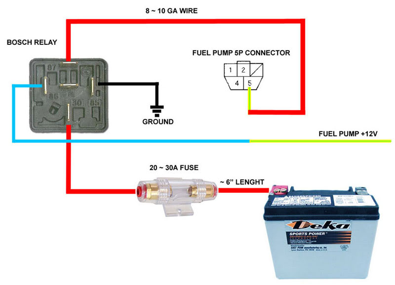
^^ Only diagram I could find... never mind the fast Vette
Correct, connect the +12v source from relay terminal #30 to the BAP +12v input
I cut the +12v going into the fuel pump plug and take the end of the wire that comes from the car and that goes into the relay.
Then take the end of the wire that would go into the plug and that gets connected to the output of the BAP, correct?
Thats all I have left, just thought I'd ask before I make the last couple cuts.
Well that and the ground on the plug, but that just splices into the BAP ground.
*The BAP can be activated by a Hobbs type pressure switch. That feature is provided so that the pump is not driven at high voltage 100% of the time, prolonging pump life. The pressure switch turns-on the BAP high voltage only when boost is ramping up. That's the ideal setup. The pump will run "normal" voltage at all other times.
If you are using a standalone ECU like AEM, you can use an output from the ECU and map it to provide a signal based on boost. I did exactly that for my Subaru STI with a FueLab pump that has a built-in speed controller. The ECU sends a +12v signal to the pump once boost reaches 3 psi and the pump switches to high speed.
Most standalone ECU's have plenty of outputs you can use to control devices. An output from the ECU provides the signal based on specified parameters in the map.
So in the ECU map, you specify:
Output X = True / On when Manifold Pressure > 3psi
I'm not too familiar with AEM, but it should be on the manuals what harness pin to use. You want to use a non-linear output, meaning it's not a varying-voltage output. You need to check what the BAP needs to switch on/off. If the input is +ve, then the ECU signal should be +ve. If the ECU only has -ve output, then you will need a relay to provide a +ve signal. #85 or #86 to ECU signal, #30 to +ve and #87 to BAP switch input. The relay is used to change polarity of the signal. You can go from +ve to -ve or vise versa
It's not that difficult, get the output pins for the ECU, connect a wire to it, test it, and use it to switch the BAP. To test, you use a multimeter/voltage tester connected to it. Then on the ECU map specify the output to switch based on RPM, say >3000 rpm. Rev up motor and when the rpm goes above 3k you should see the voltage tester light up and remain lit.
The reason I suggest using your standalone ECU instead of a Hobbs pressure switch is because pressure switches fail, and you don't want BAP to stay at low voltage on full boost when the car is expecting the fuel pump to be at high voltage.
Hope that helps!
Thread Starter
Registered User
Joined: May 2008
Posts: 3,791
Likes: 1
From: Around
Thank you, thank you, that information is invaluable.
I spoke with a few cobra guys, among reading online and they all suggest to eliminate the Hobbs switch and just allow it to be on all the time. I simply soldered the wires together that would have went to the switch.
I should have this finished up this evening then.
Thanks.
I spoke with a few cobra guys, among reading online and they all suggest to eliminate the Hobbs switch and just allow it to be on all the time. I simply soldered the wires together that would have went to the switch.
I should have this finished up this evening then.
Thanks.


Joined: Apr 2008
Posts: 369
Likes: 0
Originally Posted by siadam,Apr 3 2010, 03:35 PM
EngineerX, the diagram helps, and is basically what I have drawn up in my mind, lol.
Nice to see it on paper though, thanks.
Spoolin,

Where it shows from relay to Fuel Pump +12v, thats my hangup. The fuel pump wire in the picture I showed above is small gauge wire.
How is that plug going to help me? The fuel pump assembly "carrier" is enclosed in the tank, I'd have to drill out the top of it, to run a wire down to where the pump is and splice it, no?
Thats what confuses me.

Nice to see it on paper though, thanks.
Spoolin,
Where it shows from relay to Fuel Pump +12v, thats my hangup. The fuel pump wire in the picture I showed above is small gauge wire.
How is that plug going to help me? The fuel pump assembly "carrier" is enclosed in the tank, I'd have to drill out the top of it, to run a wire down to where the pump is and splice it, no?
Thats what confuses me.

Registered User
Joined: Mar 2006
Posts: 538
Likes: 0
From: Portland, Oregon
Correct. I run it with a constant 14v. Though some may think this may cause premature pump failure, I'm not bothered by it. The dsm guys run this setup with the same pump (walbro 255) for years without any problems. Only cut the big yellow/green wire. The black is a signal ground, not chassis ground. I was mislead by the above diagram. Do not cut this wire.
Standard 5 pin relay: #30 - 10ga fused wire to battery, #85 - ground to chassis, #86 - ylw/grn wire from ecu (other half of cut ylw/grn wire), #87 - connects to fuel pump (other half of cut ylw/grn wire). #87a not used. Hope that helps.
Standard 5 pin relay: #30 - 10ga fused wire to battery, #85 - ground to chassis, #86 - ylw/grn wire from ecu (other half of cut ylw/grn wire), #87 - connects to fuel pump (other half of cut ylw/grn wire). #87a not used. Hope that helps.