
O'Malley's Winter build

Thread Starter
Registered User
Joined: Jul 2007
Posts: 2,989
Likes: 3
Originally Posted by Torque Obsessed,Dec 31 2010, 07:55 PM
That's a great idea to run the wiring through that way. Wish we could get all the tucked cars together to share ideas and take pics...
I'm surprised you didn't need to extend the EPS wires. Where do they go from there? Up over the fender, and then in through the hole beside the headlight? Or did you send them into the engine bay another way? I ran mine over the fender and had to add over a foot of length.
I'm surprised you didn't need to extend the EPS wires. Where do they go from there? Up over the fender, and then in through the hole beside the headlight? Or did you send them into the engine bay another way? I ran mine over the fender and had to add over a foot of length.
I will update shortly... I found out the hard way that the A/C pressure switch and the horn have the same color code (blue with red stripe) so now I have to figure out which one was which since they need to be extended...


Registered User
Joined: May 2008
Posts: 3,791
Likes: 1
From: Around
Originally Posted by o'malley_808,Dec 31 2010, 04:22 PM
Yeah sorry, I should clarify that part. I didn't have to extend any of the wires running to the EPS unit/control module. The EPS wires to the steering rack will definitely need to be extended. I am also going to run them over the fender liner to behind the headlight, and then fasten the wire beneath the cross member so that they are out of sight.
I will update shortly... I found out the hard way that the A/C pressure switch and the horn have the same color code (blue with red stripe) so now I have to figure out which one was which since they need to be extended...
I will update shortly... I found out the hard way that the A/C pressure switch and the horn have the same color code (blue with red stripe) so now I have to figure out which one was which since they need to be extended...
Thread Starter
Registered User
Joined: Jul 2007
Posts: 2,989
Likes: 3
^ Yeah I still havnt finished that far, I don't have a power cable ran from the front to the trunk yet and have not quite decided how I want to connect the positive power cables together yet at the front of the vehicle...hmmm Was thinking maybe a isolated post from summit or maybe a switch but still undecided
I suppose I could just connect it temporarily.
I suppose I could just connect it temporarily.
Thread Starter
Registered User
Joined: Jul 2007
Posts: 2,989
Likes: 3
So I had a chance to do ALOT of work on the wire tuck over the weekend. I finished the passenger side and started working on the drivers side.
Here are some clearer pics of the fusebox/EPS relocation


I think the previous owner had the battery leak because my fusebox had some battle wounds and the paint was peeling in alot of places under the battery area. I'm going to sand and paint this area shortly so it doesn't look so horrendous!


Here is where I extended the harness that runs across the rad support

I then "flipped" the harness underneath the rad support so that it is hidden
Before

After

Pass wires all finished and organized. Red markers indicate where the splices are so that I can troubleshoot easily in the future if anything goes wrong


After a lot of head scratching I began working on the drivers side harness. I removed the air pump and that harness, and started noticing a lot of unnecessary items related to the air pump.
Here is the wire that runs to the air pump, I cut it... But it also runs to this box and loops into the fuse box that is normally beside the ABS unit in the engine bay.

You can unpin the power that feeds the above nest of wires from the bottom of the drivers fusebox

I then removed the existing bracket for the air pump inside the fender and in its place installed the drivers fusebox


I wanted to maintain my ABS since I want to maintain its functionality since I actually drive my car and it isn't a garage queen, not to mention it should be nice to have with 600whp
So with that being said I was trying to figure out a nice solution to routing this harness while hiding the rest. I looked inside for a way to reroute the harness directly into the fender but it wasn't an option without cutting 25+ wires so I opted out of that. Instead I used a factory hole as I pilot and cut a 1" hole as shown to route all the wires into the fender with the exception of the ABS. Since there is already alot going on in this corner you shouldn't see much since it is pretty much under the brake booster. I forgot to take a before picture but if you look at your car you will see a 1/2" hole where I drilled this one...

Separating the ABS wires from the harness you will find there are 2 shorter wires that need to be extended

Most of the wires fed through the fender well, still have to tidy, tape and loom.

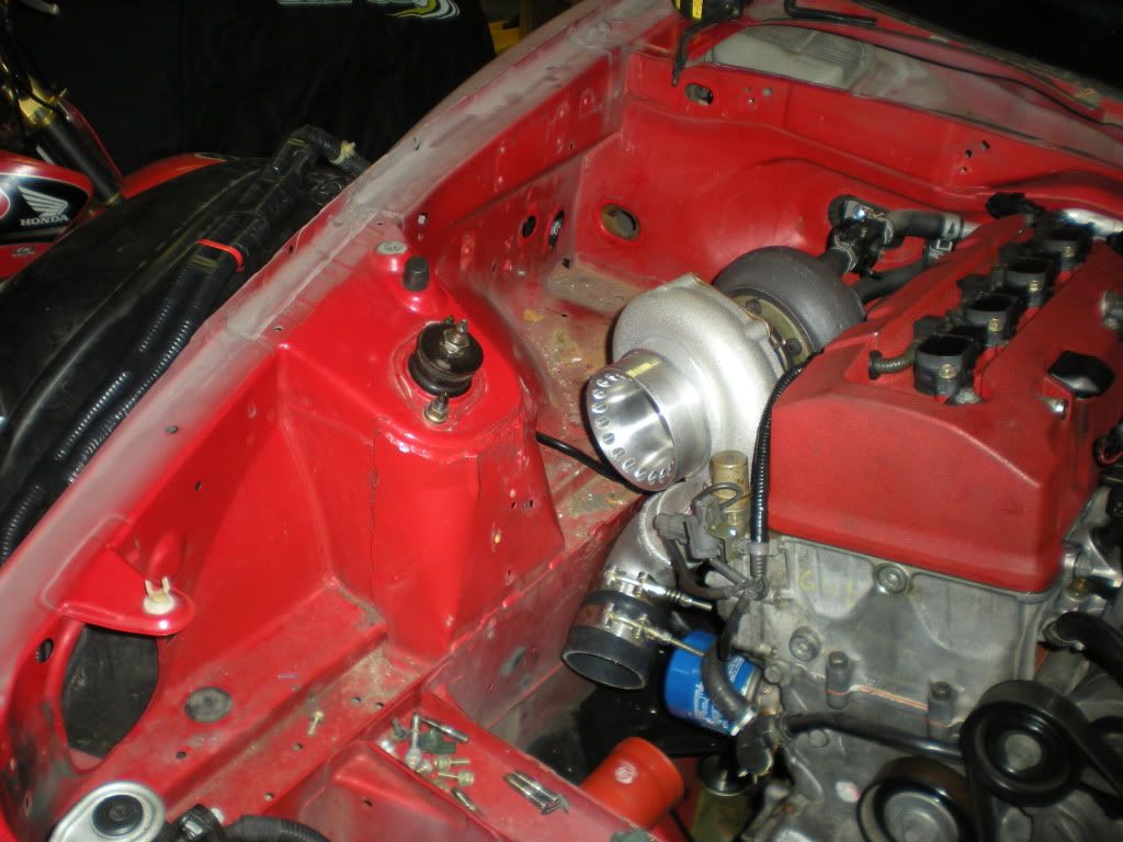
Picture of the front area of the drivers fender at the moment (soo much mud and 11 years hidden dirt under all these components Can't wait to shampoo the bay in the spring!

Here are some clearer pics of the fusebox/EPS relocation
I think the previous owner had the battery leak because my fusebox had some battle wounds and the paint was peeling in alot of places under the battery area. I'm going to sand and paint this area shortly so it doesn't look so horrendous!
Here is where I extended the harness that runs across the rad support
I then "flipped" the harness underneath the rad support so that it is hidden
Before
After
Pass wires all finished and organized. Red markers indicate where the splices are so that I can troubleshoot easily in the future if anything goes wrong
After a lot of head scratching I began working on the drivers side harness. I removed the air pump and that harness, and started noticing a lot of unnecessary items related to the air pump.
Here is the wire that runs to the air pump, I cut it... But it also runs to this box and loops into the fuse box that is normally beside the ABS unit in the engine bay.
You can unpin the power that feeds the above nest of wires from the bottom of the drivers fusebox
I then removed the existing bracket for the air pump inside the fender and in its place installed the drivers fusebox
I wanted to maintain my ABS since I want to maintain its functionality since I actually drive my car and it isn't a garage queen, not to mention it should be nice to have with 600whp
So with that being said I was trying to figure out a nice solution to routing this harness while hiding the rest. I looked inside for a way to reroute the harness directly into the fender but it wasn't an option without cutting 25+ wires so I opted out of that. Instead I used a factory hole as I pilot and cut a 1" hole as shown to route all the wires into the fender with the exception of the ABS. Since there is already alot going on in this corner you shouldn't see much since it is pretty much under the brake booster. I forgot to take a before picture but if you look at your car you will see a 1/2" hole where I drilled this one...
Separating the ABS wires from the harness you will find there are 2 shorter wires that need to be extended
Most of the wires fed through the fender well, still have to tidy, tape and loom.
Picture of the front area of the drivers fender at the moment (soo much mud and 11 years hidden dirt under all these components
Can't wait to shampoo the bay in the spring!
Registered User
Joined: May 2008
Posts: 3,791
Likes: 1
From: Around
Nice work, really coming along. Good feeling seeing the results.
I used a stereo distribution block on my car. Easy enough to pickup @ most audio/video places. I'd also recommond getting a breaker box when you run your power line to the front of the car. It can be purchased @ Autozone/Advanced. Its better than a fuse, b/c if it pops, you don't have any fuses to replace, simply hit the reset button.
I used a stereo distribution block on my car. Easy enough to pickup @ most audio/video places. I'd also recommond getting a breaker box when you run your power line to the front of the car. It can be purchased @ Autozone/Advanced. Its better than a fuse, b/c if it pops, you don't have any fuses to replace, simply hit the reset button.

Thread Starter
Registered User
Joined: Jul 2007
Posts: 2,989
Likes: 3
So I need a little bit of assistance from the wiring gurus on the forum. I am 90% complete the full wire tuck!
I ran the wire for the alternator to the drivers side rather than the passenger side at the moment because I can hide it running it under the brake booster. This wire feeds into the main fusebox on the passenger side normally. If I have to I plan on looping it through the windshield wiper tray and back to the passenger side. My question is, can I not just tie it into the the drivers fusebox on the positive? I can utilize the spot that used to be for the air pump and it will still be fused?
Circled is the wire in question

Here is the end of the wire and the drivers side fusebox im proposing to put it into...

I ran the wire for the alternator to the drivers side rather than the passenger side at the moment because I can hide it running it under the brake booster. This wire feeds into the main fusebox on the passenger side normally. If I have to I plan on looping it through the windshield wiper tray and back to the passenger side. My question is, can I not just tie it into the the drivers fusebox on the positive? I can utilize the spot that used to be for the air pump and it will still be fused?
Circled is the wire in question
Here is the end of the wire and the drivers side fusebox im proposing to put it into...


Registered User
Joined: Oct 2008
Posts: 1,637
Likes: 2
From: Portland oregon
You need to put a grommet on the new hole you cut you going to have some problems when the wires rub the metal.
And your alternator wire needs to run to the fused link in the fuse box.
And your alternator wire needs to run to the fused link in the fuse box.
Thread Starter
Registered User
Joined: Jul 2007
Posts: 2,989
Likes: 3
Originally Posted by ghettocrxsi,Jan 6 2011, 01:45 AM
You need to put a grommet on the new hole you cut you going to have some problems when the wires rub the metal.
And your alternator wire needs to run to the fused link in the fuse box.
And your alternator wire needs to run to the fused link in the fuse box.
I'm still slightly baffled by the necessity of running the alternator wire back to the pass fusebox. As long as it is fused and tied into the feed running to my battery it should suffice? I'll have to do a bit more digging around on the subject

Any update on that updated A/C kit? I'm pretty much ready for one