
FUSE BOX TUCK.


Thread Starter
Registered User
Joined: Jan 2007
Posts: 172
Likes: 0
I've had like 2 threads on here with sourcing terminals and what not, and another with removing the stupid pins off the connectors. My goal (which has not been achieved) is to use OEM connectors in between splices instead of Solder, butt connectors, and any other type of connection. I feel its the only best and most secure way of doing this without having to worry in the future. Any who this tuck I attempted (first time in my life) wasn't done with my Goal in mind (i got impatient and just did the best I could with butt connectors) and I wanted to share and see if you guys out there did it like this and well your thoughts.
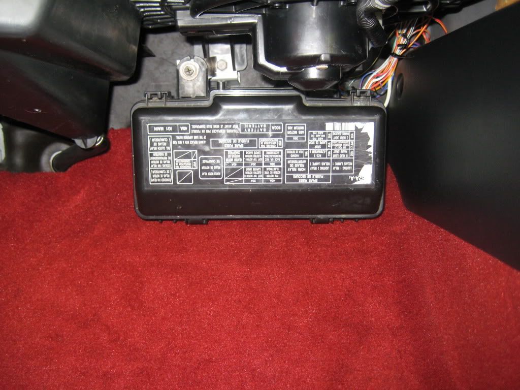
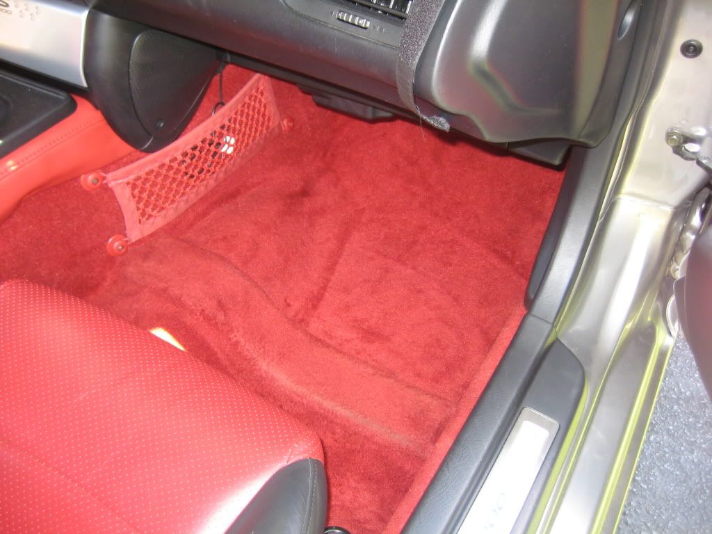
I plan on modifying this in the future but at least I got the setup done. I placed my fuse box in the pass side under dash. It is very concealed in my opinion, and I didn't use the black cover that goes around the connectors. It's mounted kinda tight in terms of the wiring in the back but hopefully that'll keep it from connections coming apart. I am kinda worried with the way I connected the wires but I did double check them before I finalized. anyone here had their fuse box tucked like this and had NO problems in the future??
Thanks for your time guys..
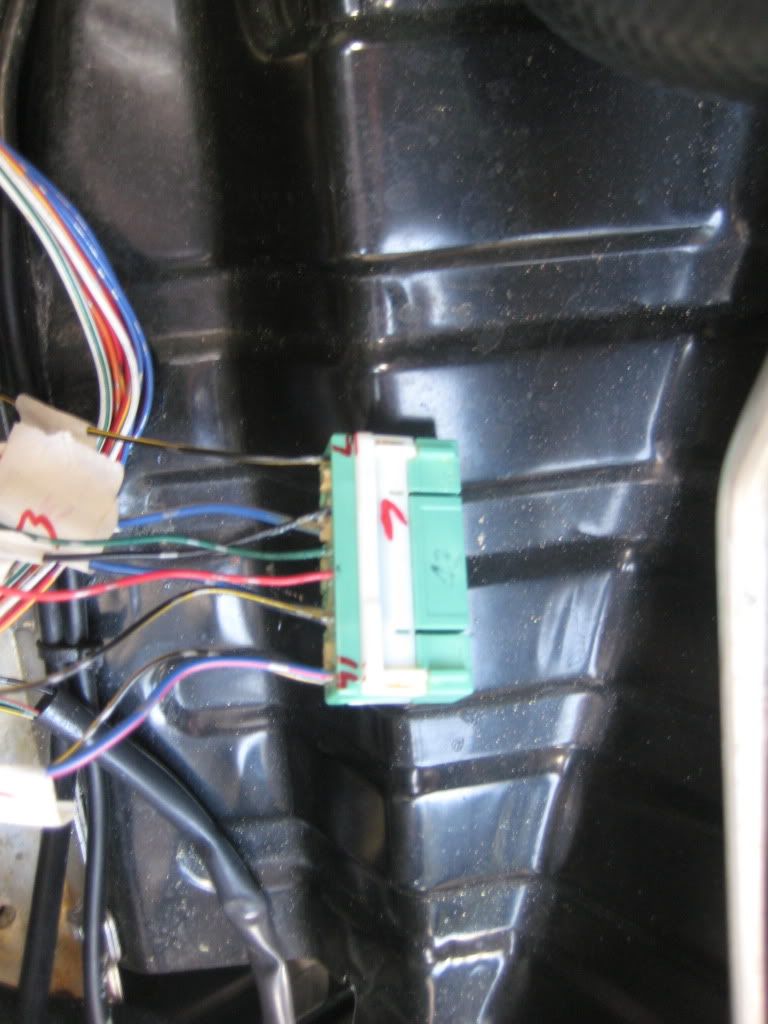
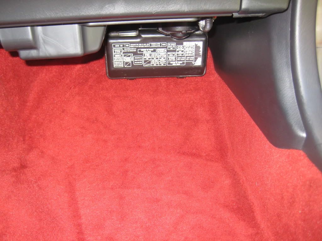
This is at the very beginning.
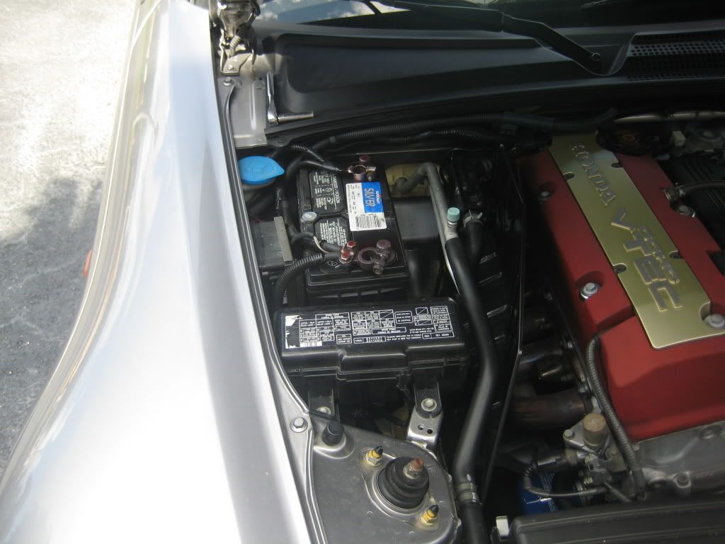


Then I removed battery/tray, EPS, and started un-looming wiring.
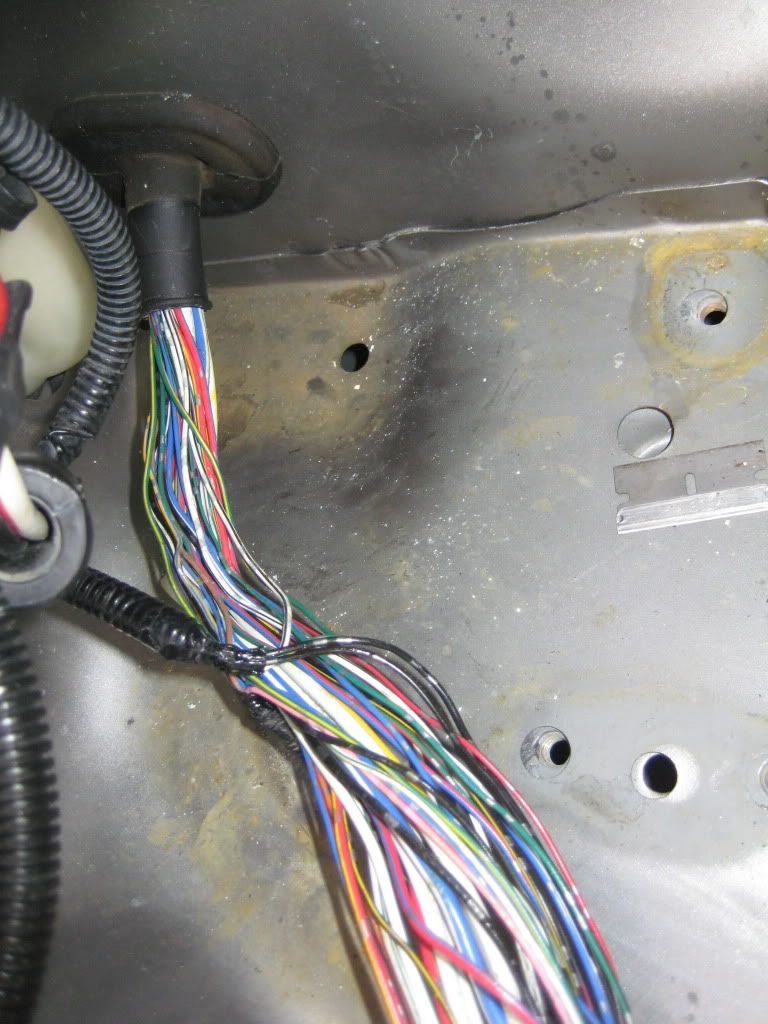
Now all the wires that could DE-PIN I did. (less wiring to hack)
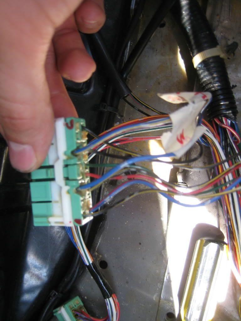
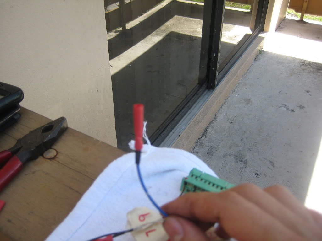
Here I set this up like this to go back and reference after I DE-PIN. I also numbered them as well as the connectors to make sure mistakes werent made.
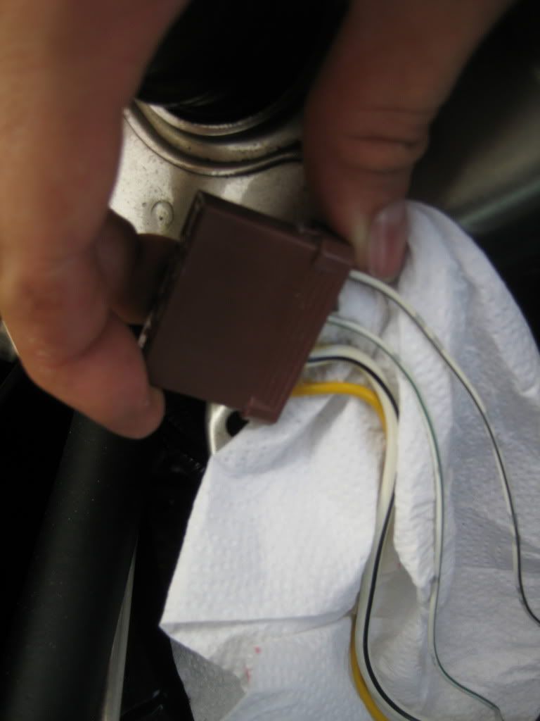
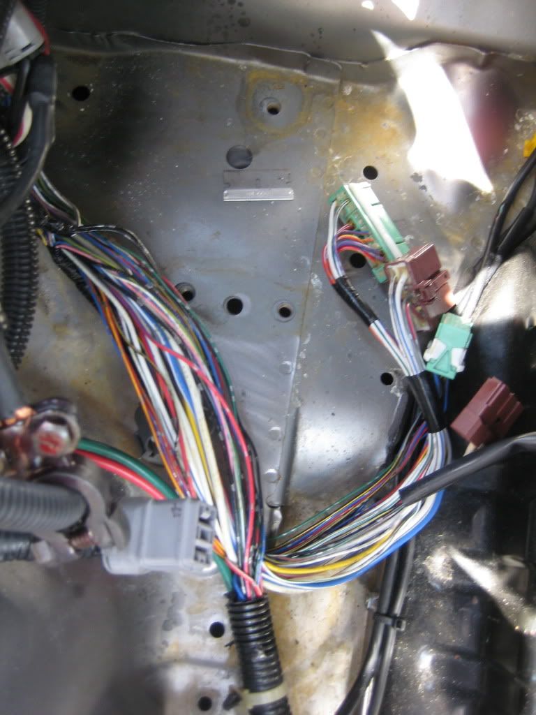
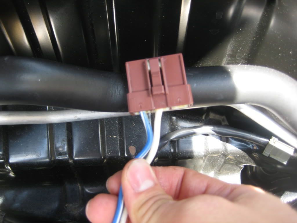
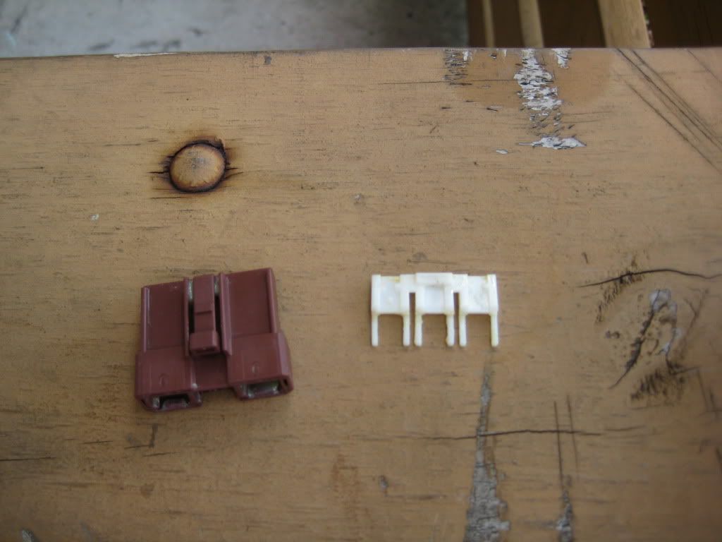
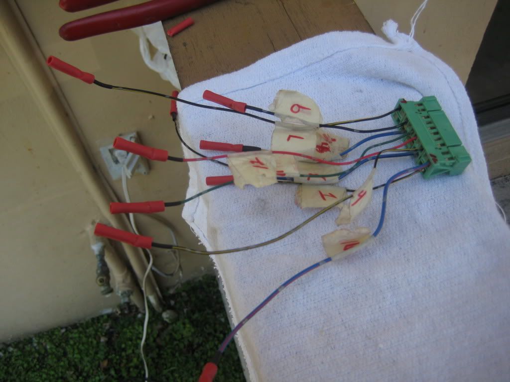
After I DE-PIN the big BROWN connectors, then came these pieces of SH**. this connector specifically I ended up cutting all the wires and THEN I figured out how to DE-PIN them (pissed me off I was getting frustrated). Originally only 3 wires from here needed to be cut and extended. Because of my frustration, all wires were cut (in which only 3 extended, the others just ran them down to the pass side).
This is how I did my connections. I double checked everything (although this is not my preference) and it was tight and snug. Future plans to change this though.
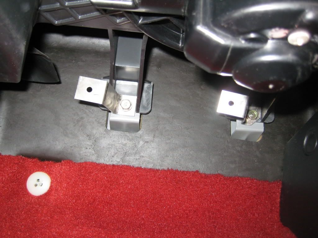
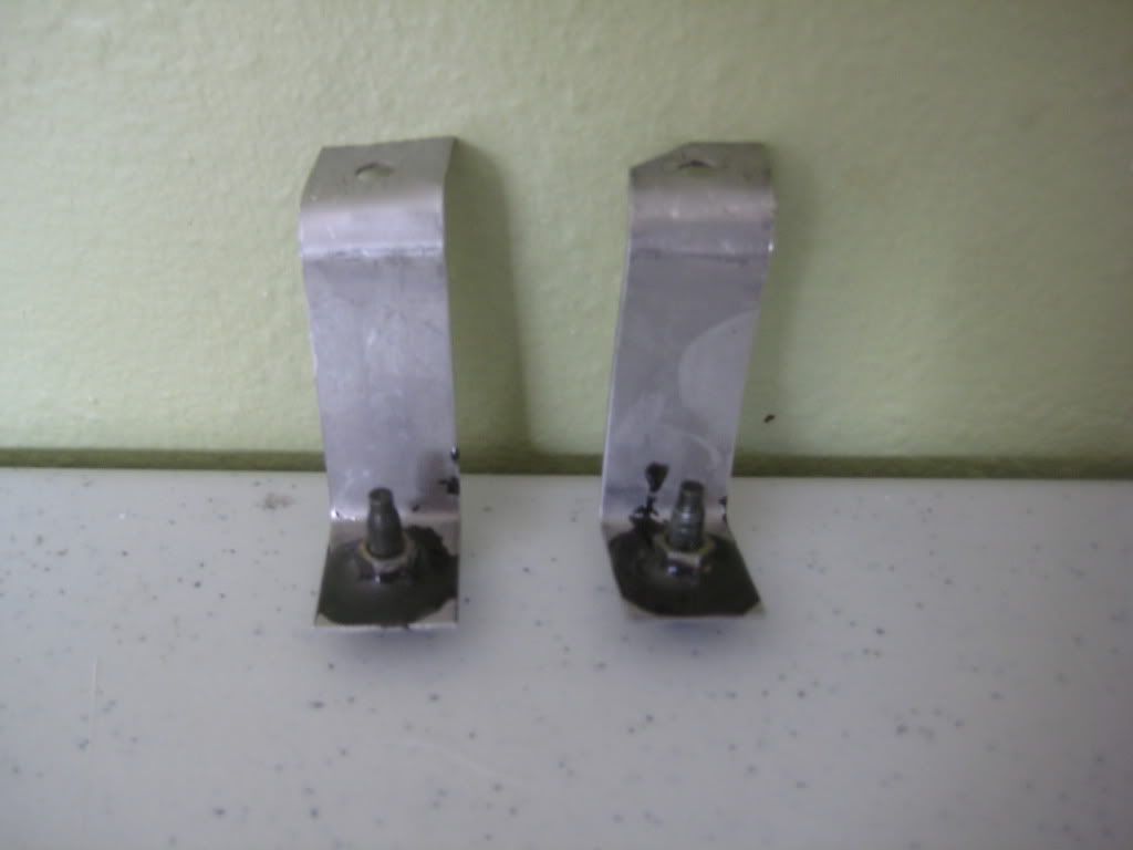
These were the brackets I used. I JB welded an 8mm nut on each bracket that way it'd be easier to mount at the end.
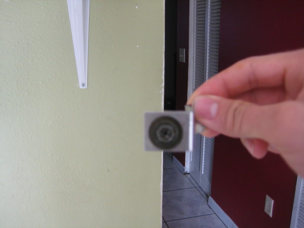
Almost DONE!!!! this pic is very scary!!
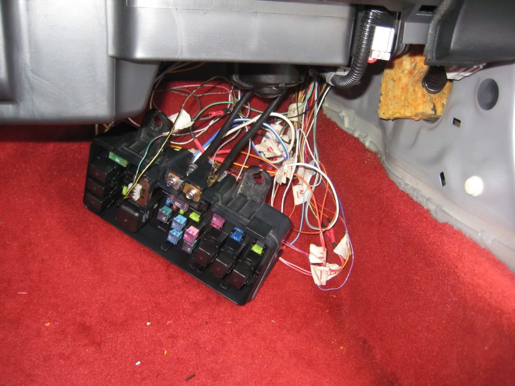
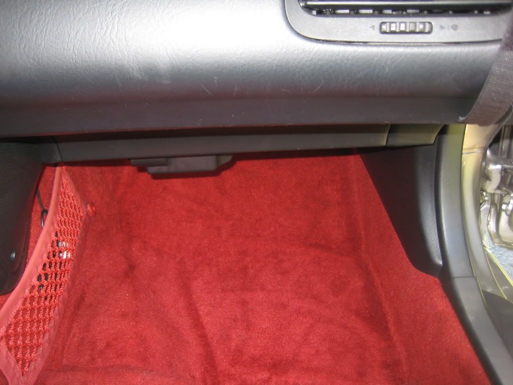
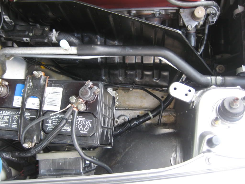
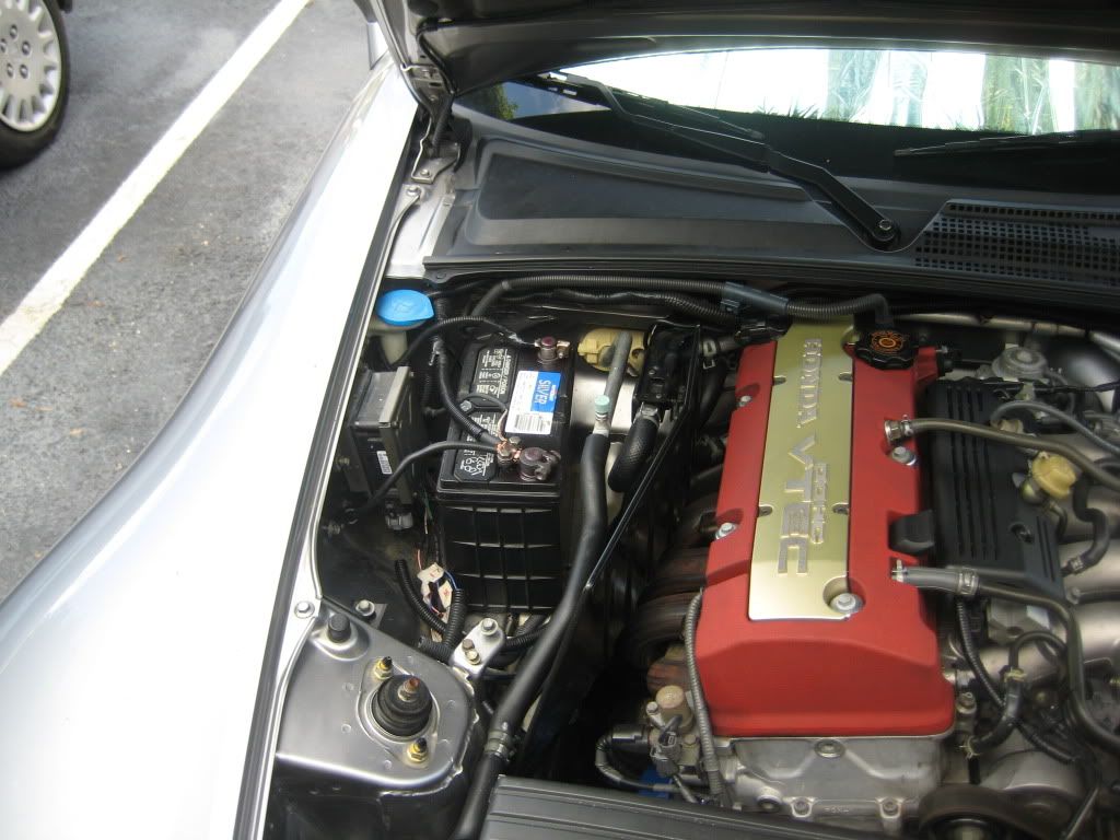
MOUNTED!!!
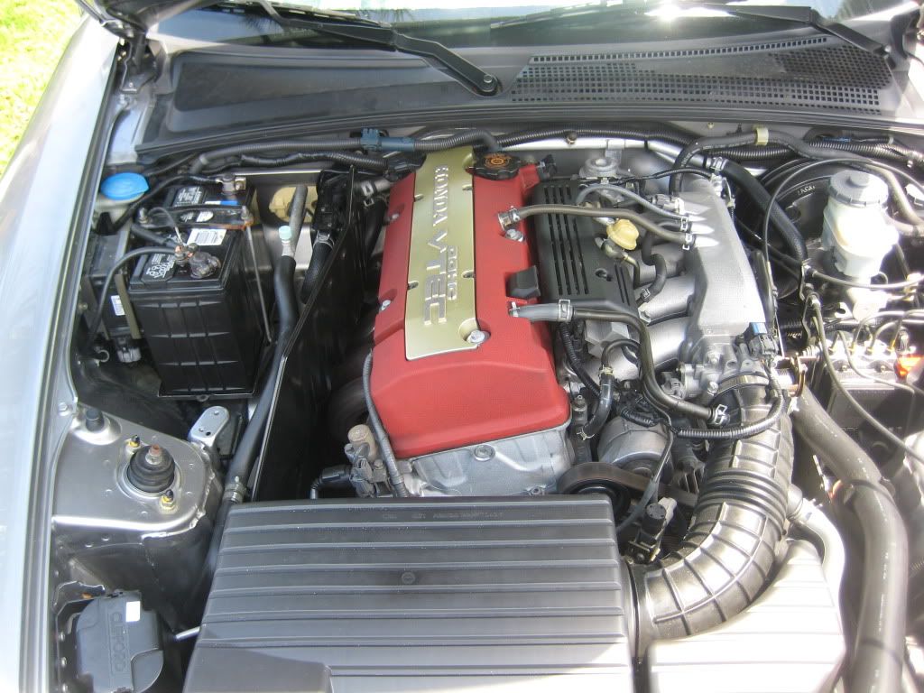
ENGINE BAY
And thats it for now..
Hope this helps some and also those to give me feedback..
Thanks guys..
I plan on modifying this in the future but at least I got the setup done. I placed my fuse box in the pass side under dash. It is very concealed in my opinion, and I didn't use the black cover that goes around the connectors. It's mounted kinda tight in terms of the wiring in the back but hopefully that'll keep it from connections coming apart. I am kinda worried with the way I connected the wires but I did double check them before I finalized. anyone here had their fuse box tucked like this and had NO problems in the future??
Thanks for your time guys..
This is at the very beginning.
Then I removed battery/tray, EPS, and started un-looming wiring.
Now all the wires that could DE-PIN I did. (less wiring to hack)
Here I set this up like this to go back and reference after I DE-PIN. I also numbered them as well as the connectors to make sure mistakes werent made.
After I DE-PIN the big BROWN connectors, then came these pieces of SH**. this connector specifically I ended up cutting all the wires and THEN I figured out how to DE-PIN them (pissed me off I was getting frustrated). Originally only 3 wires from here needed to be cut and extended. Because of my frustration, all wires were cut (in which only 3 extended, the others just ran them down to the pass side).
This is how I did my connections. I double checked everything (although this is not my preference) and it was tight and snug. Future plans to change this though.
These were the brackets I used. I JB welded an 8mm nut on each bracket that way it'd be easier to mount at the end.
Almost DONE!!!! this pic is very scary!!
MOUNTED!!!
ENGINE BAY
And thats it for now..
Hope this helps some and also those to give me feedback..
Thanks guys..


Thread Starter
Registered User
Joined: Jan 2007
Posts: 172
Likes: 0
Thanks
Thank you and I thought of doing solder which is much better, but I was worried that after soldering the brittleness of it could break it. Maybe me over thinking it. Hopefully nothing goes wrong.

Registered User

Joined: Apr 2009
Posts: 167
Likes: 0
hey iluvs2ks im currently in the process of this and need advice on de-pinning the wires .. can you briefly describe the steps to do so ? more specifically the brown plugs, i think the green plugs shouldnt be a problem .. thanks !
Trending Topics

Thread Starter
Registered User
Joined: Jan 2007
Posts: 172
Likes: 0
Dang sorry for late replys!!
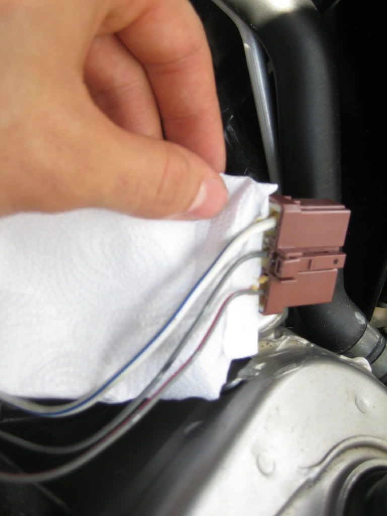
1. The white clip behind the brown plugs come off. They are a bit tight but a small fine flathead will do the trick.
2. Because you cant see much inside due to the grease, get yourself electrical parts cleaner to remove the grease.
3. once thats done you can see the little flap that holds the terminal. usually its on the side that plugs into the fusebox.
Make sense?!
making the engine bay look nice and since I plan on doing this myself, I wanted to get a feeling of whats involved.
Yes but for right now I'm just gathering my materials. I just became an RN, and am saving for a house, and I don't have a place to work on my car, plus I need a DD that way I take my time in doing this. Lots of things going on now. but I will be making a thread in the future on my build once I settle.

Thread
Thread Starter
Forum
Replies
Last Post
yuning83
S2000 Electronics
3
Mar 22, 2011 10:04 AM