
Torsen diff explained


Joined: Jul 2014
Posts: 13,819
Likes: 1,544
From: Chesterfield VA
The Torsen differential is all smoke and mirrors. I've watched this video before and don't understand how it works. 
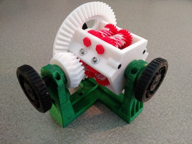
I then printed a working 3D Model of it and STILL don't understand how it works! Makes a nice model sitting on my desk. About the size of a cantaloupe. Guys are immediately attracted to it and some may even understand how it works, women don't even glance at it (just another toy).
https://www.thingiverse.com/thing:1722483
I know it works, of course. But darned if I know how.
I think our Torsens only have two sets (pairs) of worm gears. The model and video have 3 pairs.
Maybe I need a couple beers and watch both models in action again. My lack of spatial visualization won't let me solve a Rubic's cube either.
-- Chuck
I then printed a working 3D Model of it and STILL don't understand how it works!
Makes a nice model sitting on my desk. About the size of a cantaloupe. Guys are immediately attracted to it and some may even understand how it works, women don't even glance at it (just another toy).https://www.thingiverse.com/thing:1722483
I know it works, of course. But darned if I know how.
I think our Torsens only have two sets (pairs) of worm gears. The model and video have 3 pairs.
Maybe I need a couple beers and watch both models in action again. My lack of spatial visualization won't let me solve a Rubic's cube either.
-- Chuck
Thread Starter

Joined: Sep 2014
Posts: 11,345
Likes: 1,791
From what I gather, the "differential" speed part is due to the interaction of the worm gear with the worm wheel. Both having helical contact surfaces. This is the critical part - how helical gear surfaces interact, in this setup. The worm gear can move the worm wheel, but the worm wheel cannot move the worm gear.
Each mating pair of worm gears and wheels are connected, independently to each axle side (left and right). In other words, there are two separate, independent axles coming out of each side of the worm gear/wheel pair.
The worm wheel pair (left and right) can rotate in opposite directions from each other (during turns) because the worm wheel cannot move the worm gear. If you look at the video, the spur gears (end gears) are actually turning in an opposite directions. Unlike when driving straight ahead, the spur gears are not rotating, at all. The helical contact surface allows the faster side worm wheel (in a turn) or "glide" over the worm gear.
On a slippery surface, the faster spinning side worm wheel cannot turn the worm gear. Since, the two gear/wheel are connected to each other by the end spur gears and forced to spin together as a unit --- the setup is "locked-up" so that equal torque is applied to both wheels.
Man, whoever this Torsen guy was, he really is an engineering genius. This is the kinda thing that can keep you up at night, trying to understand it.
I'd love to have that toy. Gotta think about that.
Last edited by windhund116; Nov 20, 2018 at 05:12 PM.
Joined: Jul 2014
Posts: 13,819
Likes: 1,544
From: Chesterfield VA
I think it took me two or three days to print all the parts for my 3D model. Other than three very big parts the rest are small and usually in multiples. I used random colors I had in sample boxes. The main part in white in the photo is Barbie Pink in mine. I did not motorize my model so it takes 3 hands to simulate all the functions.
-- Chuck
-- Chuck

Joined: Aug 2016
Posts: 2,767
Likes: 234
From: In BOOST
From what I gather, the "differential" speed part is due to the interaction of the worm gear with the worm wheel. Both having helical contact surfaces. This is the critical part - how helical gear surfaces interact, in this setup. The worm gear can move the worm wheel, but the worm wheel cannot move the worm gear.
Each mating pair of worm gears and wheels are connected, independently to each axle side (left and right). In other words, there are two separate, independent axles coming out of each side of the worm gear/wheel pair.
The worm wheel pair (left and right) can rotate in opposite directions from each other (during turns) because the worm wheel cannot move the worm gear. If you look at the video, the spur gears (end gears) are actually turning in an opposite directions. Unlike when driving straight ahead, the spur gears are not rotating, at all. The helical contact surface allows the faster side worm wheel (in a turn) or "glide" over the worm gear.
On a slippery surface, the faster spinning side worm wheel cannot turn the worm gear. Since, the two gear/wheel are connected to each other by the end spur gears and forced to spin together as a unit --- the setup is "locked-up" so that equal torque is applied to both wheels.
Man, whoever this Torsen guy was, he really is an engineering genius. This is the kinda thing that can keep you up at night, trying to understand it.
I'd love to have that toy. Gotta think about that.
Each mating pair of worm gears and wheels are connected, independently to each axle side (left and right). In other words, there are two separate, independent axles coming out of each side of the worm gear/wheel pair.
The worm wheel pair (left and right) can rotate in opposite directions from each other (during turns) because the worm wheel cannot move the worm gear. If you look at the video, the spur gears (end gears) are actually turning in an opposite directions. Unlike when driving straight ahead, the spur gears are not rotating, at all. The helical contact surface allows the faster side worm wheel (in a turn) or "glide" over the worm gear.
On a slippery surface, the faster spinning side worm wheel cannot turn the worm gear. Since, the two gear/wheel are connected to each other by the end spur gears and forced to spin together as a unit --- the setup is "locked-up" so that equal torque is applied to both wheels.
Man, whoever this Torsen guy was, he really is an engineering genius. This is the kinda thing that can keep you up at night, trying to understand it.
I'd love to have that toy. Gotta think about that.
@Chuck S well done on the model. It's kinda...cute

Thread Starter
Joined: Sep 2014
Posts: 11,345
Likes: 1,791
Do you buy the parts for that Torsen Diff toy? Of is it a general LEGOS kinda thing?
I looked at Google, for a toy and found only cutaway real Torsen junked diffs. That would be the best, though a bit heavy and big.
I looked at Google, for a toy and found only cutaway real Torsen junked diffs. That would be the best, though a bit heavy and big.
Joined: Jul 2014
Posts: 13,819
Likes: 1,544
From: Chesterfield VA
The link to the 3D printer files for the Torsen (torque sensing) differential is linked just above the photo. There are about 30 printed parts and a dozen or so screws and washers needed to assemble the model. All the data is in the link. The shafts and bearing areas needed some light sanding to smooth them a bit and increase the clearance for less internal friction. Ummm, I wonder what the best differential oil might be? 3D printing is not for those needing instant gratification as, for example, the bevel gear housing takes about 8 hour to print. Hence several days to fabricate all the parts. Changing filament colors was supposed to help me visualize how it worked but... Actual assembly takes only few minutes.
Here's another Torsen example on a Lego car. Note if one wheel has no traction at all nothing moves but as long as there is a bit of traction or resistance to the wheel spinning torque transfers. This is where the DBW traction control comes into play by slowing the free spinning wheel and allowing torque to be sensed and transferred to the other wheel. (Yet another advantage of the late DBW cars.) Counter intuitive but using the hand brake will apply resistance to the free spinning wheel and allow torque transfer. This can be done with the brakes in the HMMWV (AKA Humvee) which uses Torsens fore and aft. There are special Torsens that avoid this. Is this version on our cars?
Looked at my model again a minute ago and it works. But I still don't know how it works. Gotta fine a way to motorize it for less than $30.
-- Chuck
3D printing is not for those needing instant gratification as, for example, the bevel gear housing takes about 8 hour to print. Hence several days to fabricate all the parts. Changing filament colors was supposed to help me visualize how it worked but... Actual assembly takes only few minutes.Here's another Torsen example on a Lego car. Note if one wheel has no traction at all nothing moves but as long as there is a bit of traction or resistance to the wheel spinning torque transfers. This is where the DBW traction control comes into play by slowing the free spinning wheel and allowing torque to be sensed and transferred to the other wheel. (Yet another advantage of the late DBW cars.) Counter intuitive but using the hand brake will apply resistance to the free spinning wheel and allow torque transfer. This can be done with the brakes in the HMMWV (AKA Humvee) which uses Torsens fore and aft. There are special Torsens that avoid this. Is this version on our cars?
Looked at my model again a minute ago and it works. But I still don't know how it works. Gotta fine a way to motorize it for less than $30.
-- Chuck
Trending Topics
Joined: Jul 2014
Posts: 13,819
Likes: 1,544
From: Chesterfield VA
Maybe you can convince a mechanical student to make one as a project.
The files in the Thingiverse link are all anyone with even a basic 3D printer needs. If you're wanting someone to do this for you just give them the link and let them download all the files. My printer will print 230mmL x 150mmW x 150mmH (seems typical for a hobby printer) and all parts fit easily on the print surface.
The files are standard "STL" (stereolithography) files which were created by CAD-type software. The STL files are then used by 3D printer software (commonly called a "slicer") to prepare machine code that can be used by a specific 3D printer. The printer then uses these instructions to print the part. 3D printing builds up layers (slices) of material layer by layer (by layer by layer by... ). Can be hypnotic to watch at first. A 200mm high model printed at 0.20mm requires 1000 layers over the entire model and if each layer takes a minute to apply it takes 1000 minutes or 17 hours for the print. Printed at a lower resolution of, say, 0.30mm will cut the time by 30%. There are a myriad other things like how fast the print head travels over the print that I don't pretend to understand (either).
-- Chuck
The files in the Thingiverse link are all anyone with even a basic 3D printer needs. If you're wanting someone to do this for you just give them the link and let them download all the files. My printer will print 230mmL x 150mmW x 150mmH (seems typical for a hobby printer) and all parts fit easily on the print surface.
The files are standard "STL" (stereolithography) files which were created by CAD-type software. The STL files are then used by 3D printer software (commonly called a "slicer") to prepare machine code that can be used by a specific 3D printer. The printer then uses these instructions to print the part. 3D printing builds up layers (slices) of material layer by layer (by layer by layer by...
). Can be hypnotic to watch at first. A 200mm high model printed at 0.20mm requires 1000 layers over the entire model and if each layer takes a minute to apply it takes 1000 minutes or 17 hours for the print. Printed at a lower resolution of, say, 0.30mm will cut the time by 30%. There are a myriad other things like how fast the print head travels over the print that I don't pretend to understand (either).-- Chuck
Last edited by Chuck S; Nov 21, 2018 at 08:33 AM.


Joined: Nov 2016
Posts: 192
Likes: 22
From: Finland
Just remember that there are different types of torsen differentials. On videos and pictures above are from Torsen type 1/a.
On S2000 Torsen is type 2/b what looks like this: https://www.s2ki.com/forums/s2000-un...embly-1161293/
Also the working principle is different between these. I haven't found videos how it works, but based on service manual the friction between planetary gears and gear case resists rotating difference between wheels.
Last edited by _valtsu_; Nov 21, 2018 at 03:40 PM.