
Engine Bay Crossmember

Thread Starter


Joined: Feb 2010
Posts: 746
Likes: 3
From: Dutchess County
Welp, my engine bay is getting sprayed again. Going to be relocating and shaving everything in there for this 2017 turbo setup. Question for the guys who have gone these routes, removing the crossmember all together (LS swap guys) or the guys who replaced the ugly oem crossmember with a tubular pipe. My question is, if the LS swap guys can run without one what's the point? Any noticable difference from removing it all together? I'm looking to replace the welded in piece with a removable one for an easier install and uninstall of the motor and trans together. But I'm gauging what diameter pipe to use? Any ideas? If you've replaced your crossmember with a removable one PLEASE POST PICTURES! 


Joined: Sep 2010
Posts: 563
Likes: 6
From: Northamptonshire
I will be doing this very soon so will do a right up on it,I couldn't find a diy on this either....will be doing things a little different to what I've seen also, as to mounting points and how it's put togeather/welded.some people seem to cut the oem one out without taking note of how it was constructed. Can't see it being to difficult tho.
Registered User
Joined: Jan 2011
Posts: 4,624
Likes: 10
Hey OP.
ImportMuscle claims that removing the front cross member is OK for their swap because the motor mount plates are rigid-mounted to the frame rails. Therefore the motor becomes "one" with the chassis and acts as a stiffening component itself. The motor acts as a replacement for the OEM cross member. Take that for what you will.
Most, if not all, of the turbo builds that I've seen on F-series engines that remove the OEM cross member end up replacing it with something custom made out of round or square tube. I'd say you DEFINITELY want to replace it if you remove it. While mine was out, we jacked up the front-left corner a bit and visibly watched it flex relative to the passenger side.
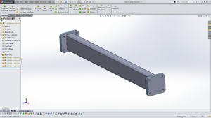
My initial design was a copy-cat of baZurk's that he made for his turbo build. It used 2.5" square tube with 1/8" wall thickness, 4" square x 1/4" thick flanges welded onto each end, and 4" square x 1/2" thick mating flanges welded onto the frame rails. It used M10x1.5 flange bolts to attach the cross member to the frame rail flanges. The bar was welded at 45 deg. relative to the flanges. Picture of design below.
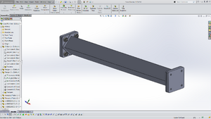
I had to scrap this design due to interference with my coolant lines and a few other things. The final design was using a 1.5" x 3.0" rectangular tube with 1/8" wall thickness, 3-11/16" square flanges (same thicknesses as previous design), still using M10 bolts. We also ended up notching and welding the bar slightly in one spot for additional clearance to a radiator hose. The result was pretty dang hefty, at least as heavy as the OEM cross member that was removed.
Surprisingly I don't have a picture of it mounted in place, and I didn't drive the car today else I'd go snap one now. I'll try to get one for you next time I drive it.
ImportMuscle claims that removing the front cross member is OK for their swap because the motor mount plates are rigid-mounted to the frame rails. Therefore the motor becomes "one" with the chassis and acts as a stiffening component itself. The motor acts as a replacement for the OEM cross member. Take that for what you will.
Most, if not all, of the turbo builds that I've seen on F-series engines that remove the OEM cross member end up replacing it with something custom made out of round or square tube. I'd say you DEFINITELY want to replace it if you remove it. While mine was out, we jacked up the front-left corner a bit and visibly watched it flex relative to the passenger side.
My initial design was a copy-cat of baZurk's that he made for his turbo build. It used 2.5" square tube with 1/8" wall thickness, 4" square x 1/4" thick flanges welded onto each end, and 4" square x 1/2" thick mating flanges welded onto the frame rails. It used M10x1.5 flange bolts to attach the cross member to the frame rail flanges. The bar was welded at 45 deg. relative to the flanges. Picture of design below.

I had to scrap this design due to interference with my coolant lines and a few other things. The final design was using a 1.5" x 3.0" rectangular tube with 1/8" wall thickness, 3-11/16" square flanges (same thicknesses as previous design), still using M10 bolts. We also ended up notching and welding the bar slightly in one spot for additional clearance to a radiator hose. The result was pretty dang hefty, at least as heavy as the OEM cross member that was removed.

Surprisingly I don't have a picture of it mounted in place, and I didn't drive the car today else I'd go snap one now. I'll try to get one for you next time I drive it.


Registered User
Joined: Jan 2011
Posts: 4,624
Likes: 10
Solidworks is definitely one of the more user-friendly CAD systems that I've had the pleasure of working with. If you're proficient with computers (i.e. born in the 80's or later) then I think its certainly something you can pick up on your own. Especially with as many tutorials as you can find for free online in places like YouTube. So far I've worked with Solidworks, Pro Engineer (now Creo), Inventor, and a janky little software called Alibre Design (now Geomagic?). I can firmly say that Solidworks has been my favorite by far. I watch my friends program in Creo and I just sit there scratching my head, knowing there's much easier ways to do the same stuff in Solidworks.
Thread Starter
Joined: Feb 2010
Posts: 746
Likes: 3
From: Dutchess County
Hey OP.
ImportMuscle claims that removing the front cross member is OK for their swap because the motor mount plates are rigid-mounted to the frame rails. Therefore the motor becomes "one" with the chassis and acts as a stiffening component itself. The motor acts as a replacement for the OEM cross member. Take that for what you will.
Most, if not all, of the turbo builds that I've seen on F-series engines that remove the OEM cross member end up replacing it with something custom made out of round or square tube. I'd say you DEFINITELY want to replace it if you remove it. While mine was out, we jacked up the front-left corner a bit and visibly watched it flex relative to the passenger side.
My initial design was a copy-cat of baZurk's that he made for his turbo build. It used 2.5" square tube with 1/8" wall thickness, 4" square x 1/4" thick flanges welded onto each end, and 4" square x 1/2" thick mating flanges welded onto the frame rails. It used M10x1.5 flange bolts to attach the cross member to the frame rail flanges. The bar was welded at 45 deg. relative to the flanges. Picture of design below.
I also like how Bobby Randolph made his and I'm looking at that route also.


Last edited by KillerCom; Feb 8, 2017 at 08:18 PM.
Trending Topics
Registered User
Joined: Jan 2011
Posts: 4,624
Likes: 10
We actually welded the thick flanges to the frame rails, then drilled and tapped the M10 holes all the way through the plates and the frame rails. So the bolt actually engages the frame rail as well just for a little extra thread length.
I remember seeing Bobby's setup when he made it; very nice work indeed.
Thread Starter
Joined: Feb 2010
Posts: 746
Likes: 3
From: Dutchess County
I'm not sure what you mean here... There aren't any nuts in my setup. The thicker plates that are welded to the frame rails have M10 tapped holes. That's what the M10 bolts thread into when you bolt on the cross member. The four bolt heads are easily accessible with a wrench, though a swivel socket makes them even easier to tighten/remove.
We actually welded the thick flanges to the frame rails, then drilled and tapped the M10 holes all the way through the plates and the frame rails. So the bolt actually engages the frame rail as well just for a little extra thread length.
I remember seeing Bobby's setup when he made it; very nice work indeed.


