
Greddy Turbo Install

Thread Starter
Registered User
Joined: Apr 2007
Posts: 1,172
Likes: 0
From: Irvine/Orange
Started another project. Sadly I dont think I will be finished with it until the end of March. Anywho, I present the first unofficial steering column gauge pod!!!

I decided to go with PLX since Innovate's wideband kit was back ordered. Thankfully I'm glad I went this route since I can daisy chain a bunch of sensors to this one gauge. However, build quality is SEVERELY suffering. I have about 10 tiny dust specs in behind the gauge's glass. Also, my electronic boxes are supposed to be interlockable but are so far off spec that they'll never snap together. Nevertheless, when I turned on the gauge, OMG!!! The OLED is so BEAUTIFUL! The viewing angle is insane too. I can tilt it at any angle and as long as I can see the OLED screen, I will be able to read the gauge.


I couldn't find any gauge pod that would be suitable for my project so I picked up some lexan plastic/glass from my local Home Depot.

Using a 2" hole saw, I cut open an opening for the gauge. Once the hole is created, I placed the gauge inside and traced around the gauge for the outer trim ring.

After much cutting sanding etc... the final result. I left a tab at the end so I could secure it to the steering column plastic cover.

Now onto the column. This piece is a bit difficult to get too. All you need to do is remove the lower steering column cover by removing 3 philips screws. Then loosten (NOT REMOVE) two 12mm bolts that hold the steering column up. This will lower the steering column about 2cm which will allow you to pop off the upper column piece.

Cut a hole!

Test fitting

Test fitting
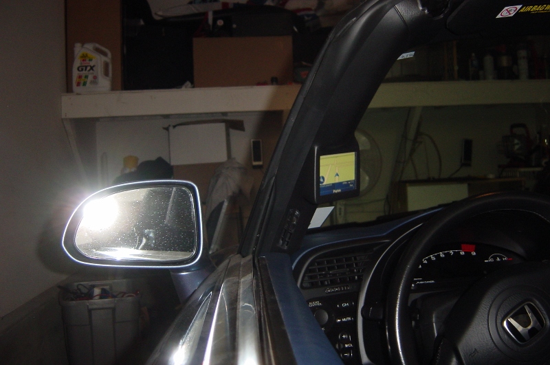
Overall I'm confident this will work. The placement is set to block anything in the gauge pods way except the speedo. If I want to see the check engine light, mileage, trip meter, I will have to lean to the side. Other than that, it should look nearly stock once done.
Update - 3-23-08
Today I got quite a bit done. The general shape is laid out. All that is left is filling and sanding which will take awhile since I'm going for perfection. To prove it, all measurements are actually done with a caliper and will be a mirror image in shape up to 0.5mm.

Here is the bezel glued to the steering column cover. Note that the bezel is now scratched and marred so the fiberglass can bond to it.


Some fiberglass mat cut out for the general shape of the gauge.

I didn't take a picture of the fiberglass part which sucks because it would've showed the general skeleton of the gauge pod.... nevertheless, hopefully you can get an idea how it looked with the filler on top of it.


Here it is sanded. Probably around 80% done as I still have a lot of filling and sanding to do. But at least from here, you can get a better idea what the final product will look like.

Black dots denote where additional sanding is needed.

Some writing to show where some filling is needed

More filling.
3-27-08
Finished... well the pod only. Heres the progress I made in the last few days

Filled all imperfections and sanded it down to smootly with 2000 grit sand paper


Sprayed with primer


Painted with satin black

3-28 to 3-30
Finally got everything done this weekend and its looking great. I didn't take many pics during the actual gauge install since i loaned out my new digi cam for the weekend. I actually had to pull an 6 year old sony out of my closet which would only take 1-2 shots before needing a recharge.

Here's the wiring harness I cooked up which will give the plx modules power. Note that I put a extra cig adapter which I was going to use to power my a-pillar nav. It turns out it was a bad idea since it overloads the fuse box terminals and will cause your accessory lights fuse to burn out. I learned this the hard way by having a cop pull me over at 1:30am for no rear lights.


Here are the two modules. The larger one runs the digital gauge while the smaller one runs the wideband. I actually was able to make the two modules lock together. Of course, this required almost 30 mins of constant hammering with a plastic mallet.

Here is a shot of the berk TP with two bungs. The one on the left is the OEM O2 sensor and the one on the right is the PLX wideband. The yellow line shows the layout of the wiring for the wideband.

Another shot of how the wiring is looped over the transmission. To secure the wiring, you can zip tie it to the OEM O2 sensor harness.

Again, continue routing the wiring in yellow along with the OEM 02 sensor harness (circled in red)

More routing.

Once you get here. Just work the wiring to the top of the engine bay (near the Clutch fluid reservoir) by following one of the existing wire-looms.
The rest of the wiring should be easy... as a result ... instruction ends here and some final shots are enclosed
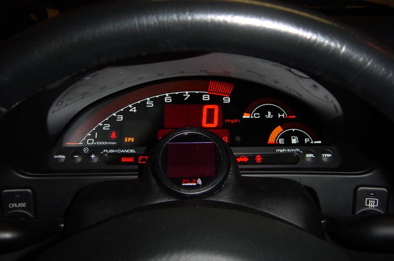

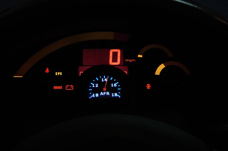

I decided to go with PLX since Innovate's wideband kit was back ordered. Thankfully I'm glad I went this route since I can daisy chain a bunch of sensors to this one gauge. However, build quality is SEVERELY suffering. I have about 10 tiny dust specs in behind the gauge's glass. Also, my electronic boxes are supposed to be interlockable but are so far off spec that they'll never snap together. Nevertheless, when I turned on the gauge, OMG!!! The OLED is so BEAUTIFUL! The viewing angle is insane too. I can tilt it at any angle and as long as I can see the OLED screen, I will be able to read the gauge.
I couldn't find any gauge pod that would be suitable for my project so I picked up some lexan plastic/glass from my local Home Depot.
Using a 2" hole saw, I cut open an opening for the gauge. Once the hole is created, I placed the gauge inside and traced around the gauge for the outer trim ring.
After much cutting sanding etc... the final result. I left a tab at the end so I could secure it to the steering column plastic cover.
Now onto the column. This piece is a bit difficult to get too. All you need to do is remove the lower steering column cover by removing 3 philips screws. Then loosten (NOT REMOVE) two 12mm bolts that hold the steering column up. This will lower the steering column about 2cm which will allow you to pop off the upper column piece.
Cut a hole!
Test fitting
Test fitting
Overall I'm confident this will work. The placement is set to block anything in the gauge pods way except the speedo. If I want to see the check engine light, mileage, trip meter, I will have to lean to the side. Other than that, it should look nearly stock once done.
Update - 3-23-08
Today I got quite a bit done. The general shape is laid out. All that is left is filling and sanding which will take awhile since I'm going for perfection. To prove it, all measurements are actually done with a caliper and will be a mirror image in shape up to 0.5mm.
Here is the bezel glued to the steering column cover. Note that the bezel is now scratched and marred so the fiberglass can bond to it.
Some fiberglass mat cut out for the general shape of the gauge.
I didn't take a picture of the fiberglass part which sucks because it would've showed the general skeleton of the gauge pod.... nevertheless, hopefully you can get an idea how it looked with the filler on top of it.
Here it is sanded. Probably around 80% done as I still have a lot of filling and sanding to do. But at least from here, you can get a better idea what the final product will look like.
Black dots denote where additional sanding is needed.
Some writing to show where some filling is needed
More filling.
3-27-08
Finished... well the pod only. Heres the progress I made in the last few days
Filled all imperfections and sanded it down to smootly with 2000 grit sand paper
Sprayed with primer
Painted with satin black
3-28 to 3-30
Finally got everything done this weekend and its looking great. I didn't take many pics during the actual gauge install since i loaned out my new digi cam for the weekend. I actually had to pull an 6 year old sony out of my closet which would only take 1-2 shots before needing a recharge.
Here's the wiring harness I cooked up which will give the plx modules power. Note that I put a extra cig adapter which I was going to use to power my a-pillar nav. It turns out it was a bad idea since it overloads the fuse box terminals and will cause your accessory lights fuse to burn out. I learned this the hard way by having a cop pull me over at 1:30am for no rear lights.
Here are the two modules. The larger one runs the digital gauge while the smaller one runs the wideband. I actually was able to make the two modules lock together. Of course, this required almost 30 mins of constant hammering with a plastic mallet.
Here is a shot of the berk TP with two bungs. The one on the left is the OEM O2 sensor and the one on the right is the PLX wideband. The yellow line shows the layout of the wiring for the wideband.
Another shot of how the wiring is looped over the transmission. To secure the wiring, you can zip tie it to the OEM O2 sensor harness.
Again, continue routing the wiring in yellow along with the OEM 02 sensor harness (circled in red)
More routing.
Once you get here. Just work the wiring to the top of the engine bay (near the Clutch fluid reservoir) by following one of the existing wire-looms.
The rest of the wiring should be easy... as a result ... instruction ends here and some final shots are enclosed


Registered User
Joined: Jan 2006
Posts: 8,255
Likes: 0
From: Victorville
Originally Posted by PitchBlackAP1,Mar 22 2008, 12:54 AM
do have to add a bov to the greddy kit i dont see in page one where there was a place for it i was just wondering if the kit comes with it or not
 ..
..Why doesn't someone with greddy crank the boost for a pull or two on the dyno 12psi won't hurt anything
 just to see what it makes. I mean its what 10hp per psi or something along those lines so going from 7-8psi (260-80) to 10 is 300whp 2 more pounds would be like 330 or am I in fantasy land haha.
Joined: Jan 2008
Posts: 9,570
Likes: 3
From: New Jersey
Originally Posted by smirfs2k05,Mar 22 2008, 01:33 AM
No it doesn't..venting compressed air the the atmosphere won't fly with carb and epa ..
Why doesn't someone with greddy crank the boost for a pull or two on the dyno 12psi won't hurt anything just to see what it makes. I mean its what 10hp per psi or something along those lines so going from 7-8psi (260-80) to 10 is 300whp 2 more pounds would be like 330 or am I in fantasy land haha.
..Why doesn't someone with greddy crank the boost for a pull or two on the dyno 12psi won't hurt anything
just to see what it makes. I mean its what 10hp per psi or something along those lines so going from 7-8psi (260-80) to 10 is 300whp 2 more pounds would be like 330 or am I in fantasy land haha.Registered User
Joined: Jan 2006
Posts: 8,255
Likes: 0
From: Victorville
Originally Posted by JoeyBalls,Mar 22 2008, 07:03 AM
good question I am aiming for 9-10psi, but too much of a pussy to go any higher then that

 haha jk but if I ever get the cash together for a greddy kit I wouldn't mind turning it up for just a quick pull.

