
DIY Valve Adjustment


Thread Starter


Joined: May 2001
Posts: 6,206
Likes: 15
From: Bergen County, NJ
when NY metro members had a tech-day in august, in courtesy of Dave (DaveOnLI), I was one of the lucky one to do the valve adjustment and this is the documentary.
before begin, you should have very good knowledge on this or you should have expert with you to do this. this document is just to show you what type of work is involved and some information regarding F20C specific information.
I'd like to thank Dave for hosting, Eliot (defender), Bill (Billman250), and Kristin for helping me with this.
first, people who helped me.

Eliot & Billman.
before begin, you should have very good knowledge on this or you should have expert with you to do this. this document is just to show you what type of work is involved and some information regarding F20C specific information.
I'd like to thank Dave for hosting, Eliot (defender), Bill (Billman250), and Kristin for helping me with this.
first, people who helped me.
Eliot & Billman.
Thread Starter
Joined: May 2001
Posts: 6,206
Likes: 15
From: Bergen County, NJ
steps required.
1) remove valve cover.
2) turn the crank.
3) adjust valve for cylinder #1.
4) repeat 2 & 3 for cylinder 4, 3,& 2.
5) reinstall valve cover.
it sounds too simple isn't it.
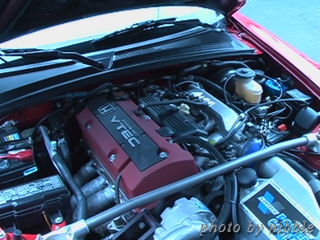
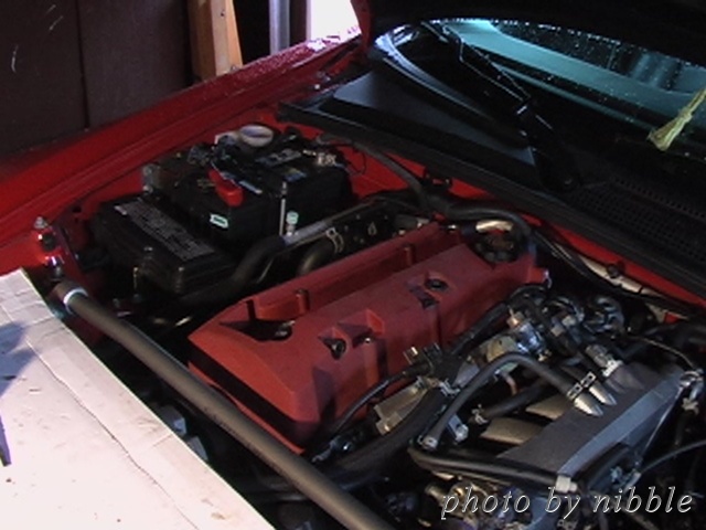
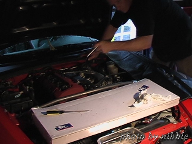
this is where it begins. opening the hood.
this tool to remove spark plug cover.
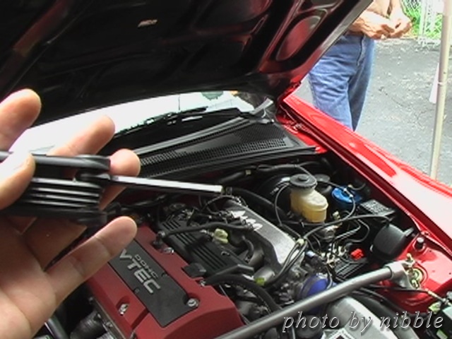
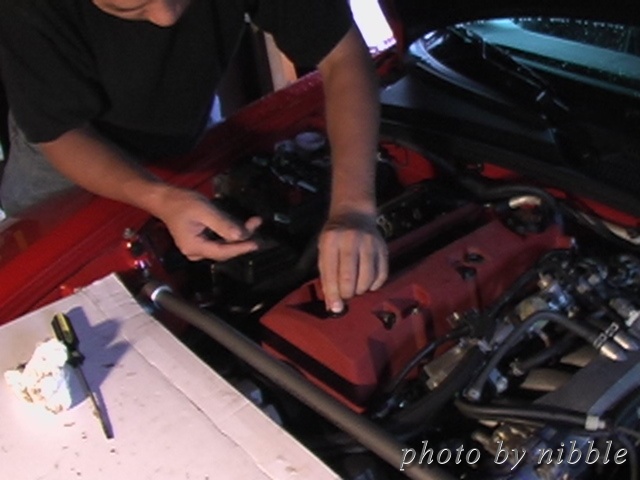
removing spark plug cover.
spark plug cover removed.
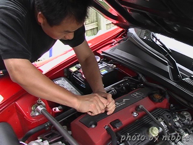
spark plug is still in the hole. we just removed the harness.
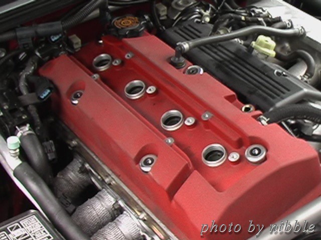
Bill's trick : lift all spark plug connectors first about an inch then remove harness.
1) remove valve cover.
2) turn the crank.
3) adjust valve for cylinder #1.
4) repeat 2 & 3 for cylinder 4, 3,& 2.
5) reinstall valve cover.
it sounds too simple isn't it.
this is where it begins. opening the hood.
this tool to remove spark plug cover.
removing spark plug cover.
spark plug cover removed.
spark plug is still in the hole. we just removed the harness.
Bill's trick : lift all spark plug connectors first about an inch then remove harness.
Thread Starter
Joined: May 2001
Posts: 6,206
Likes: 15
From: Bergen County, NJ
use a pair of plier to remove hoses.
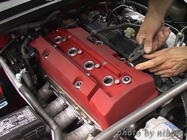
I forgot what you call this but this magnetic part had some metal shave on it. of course, it was wiped with clean cloth.
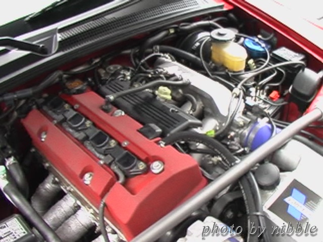
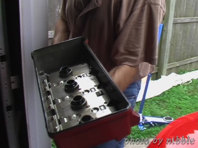
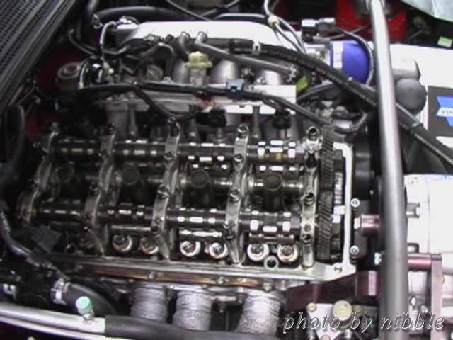
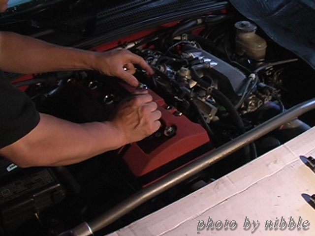
removed valve cover. make sure it's clean and no moisture.
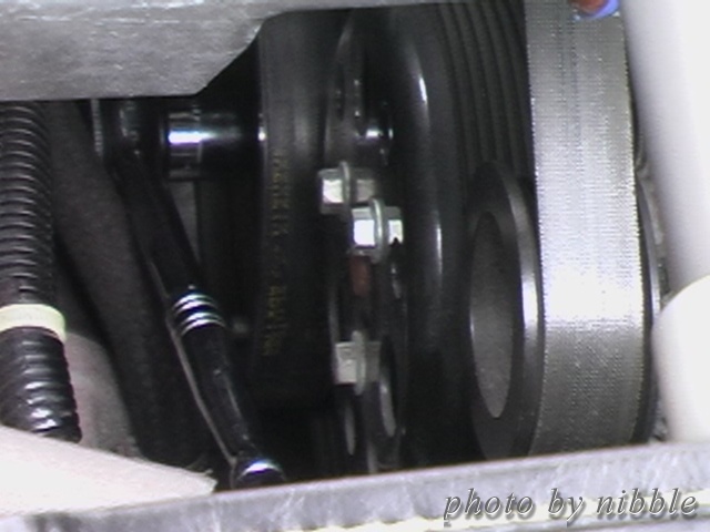
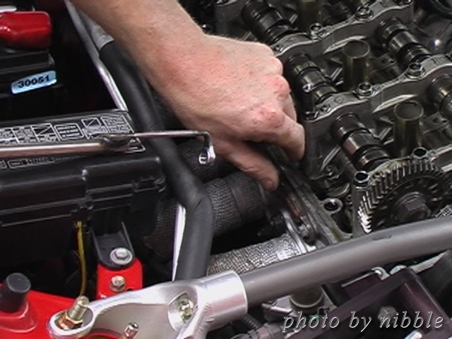
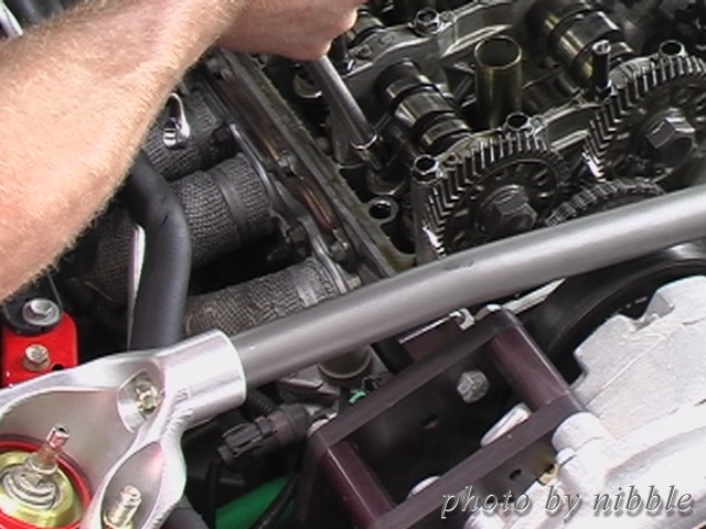
this is crank we turned to get cams aligned properly. we left the wrench there for duration of this work and little more....
next 2 photos show how it is aligned.
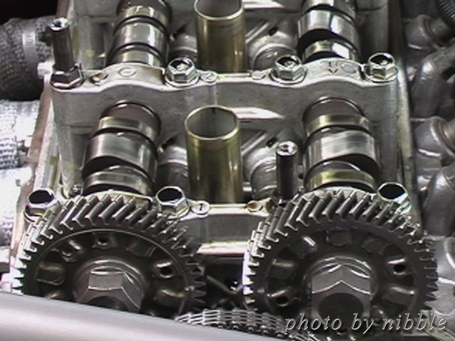
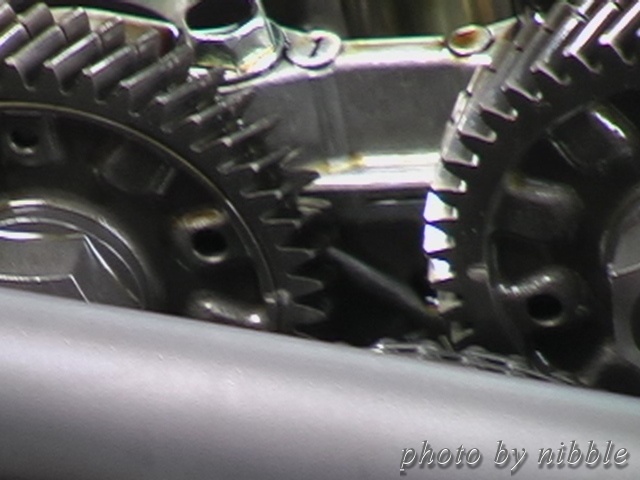
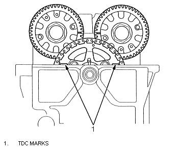
this is according to the manual.
once it's aligned, cylinder #1 is ready for valve adjustment.
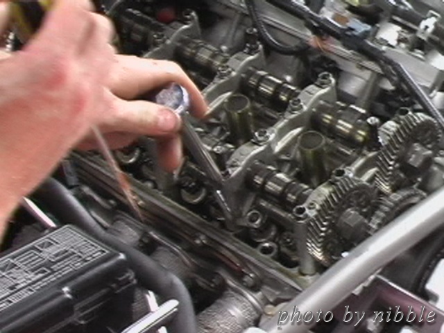
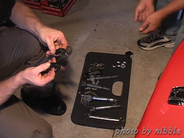
first, use these feeler to measure the gap.
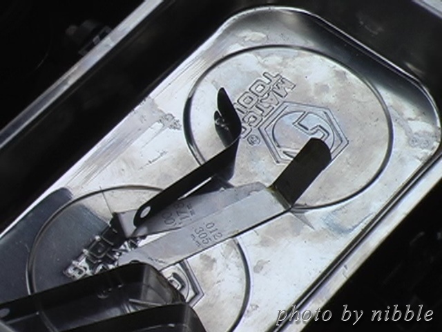
though this is not cyl#1, just want to show you measureing the gap.
The adjusting screw itself is a just a minus screw which you can turn it with screw driver but not until loosen locknuts on outer ream - I believe it's 7mm. so, first, loosen the locknut. turn the adjusting screw to desired gap. hold the screw. tighten the locknut.
Bill had his own special tool for this.
I forgot what you call this but this magnetic part had some metal shave on it. of course, it was wiped with clean cloth.
removed valve cover. make sure it's clean and no moisture.
this is crank we turned to get cams aligned properly. we left the wrench there for duration of this work and little more....
next 2 photos show how it is aligned.
this is according to the manual.
once it's aligned, cylinder #1 is ready for valve adjustment.
first, use these feeler to measure the gap.
though this is not cyl#1, just want to show you measureing the gap.
The adjusting screw itself is a just a minus screw which you can turn it with screw driver but not until loosen locknuts on outer ream - I believe it's 7mm. so, first, loosen the locknut. turn the adjusting screw to desired gap. hold the screw. tighten the locknut.
Bill had his own special tool for this.
Thread Starter
Joined: May 2001
Posts: 6,206
Likes: 15
From: Bergen County, NJ
the manual drew it this way.

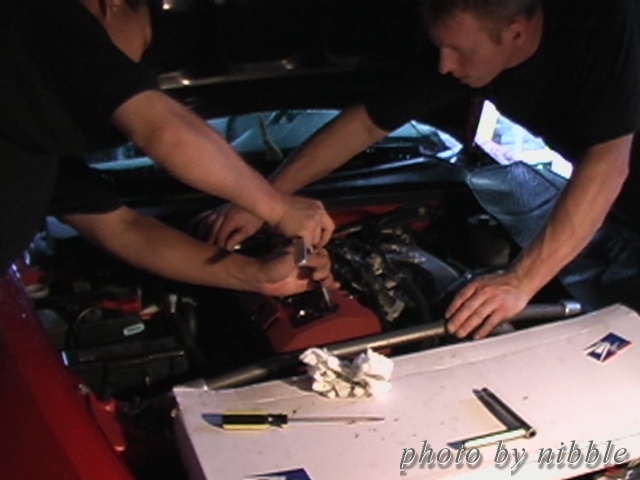
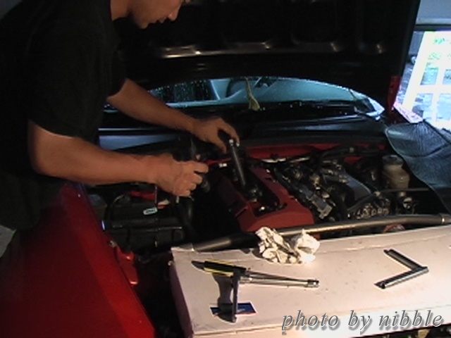
bill's adjusting the valve with his own tool. although illustration shows using regular wrench, it's almost impossible to get that wrench like that in this small engine bay. Bill fabricated this wrench just to do the VA.
once it's done, measure it again to make sure it hasn't turned. measurement should be,
intake (closer to driver side for LHD) : 0.008 - 0.010 in (0.21 - 0.25 mm)
exhaust (closer to passenger side for LHD) : 0.010 - 0.011 in (0.25 - 0.29 mm)
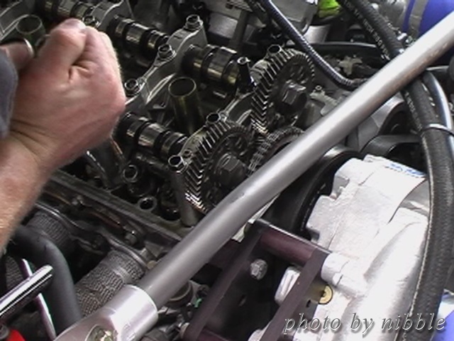
once cyl#1 is done, turn the crank clockwise to have cyl#3 cam pointing outward like \ / ... . and adjust valve on cyl#3 as same method as before. repeat this for cylinder #4, then #2. The order of adjusting valve is as follow.
cylinder #1
cylinder #3
cylinder #4
cylinder #2
you could mix it but why would you make it harder?
bill's adjusting the valve with his own tool. although illustration shows using regular wrench, it's almost impossible to get that wrench like that in this small engine bay. Bill fabricated this wrench just to do the VA.
once it's done, measure it again to make sure it hasn't turned. measurement should be,
intake (closer to driver side for LHD) : 0.008 - 0.010 in (0.21 - 0.25 mm)
exhaust (closer to passenger side for LHD) : 0.010 - 0.011 in (0.25 - 0.29 mm)
once cyl#1 is done, turn the crank clockwise to have cyl#3 cam pointing outward like \ / ... . and adjust valve on cyl#3 as same method as before. repeat this for cylinder #4, then #2. The order of adjusting valve is as follow.
cylinder #1
cylinder #3
cylinder #4
cylinder #2
you could mix it but why would you make it harder?
Thread Starter
Joined: May 2001
Posts: 6,206
Likes: 15
From: Bergen County, NJ
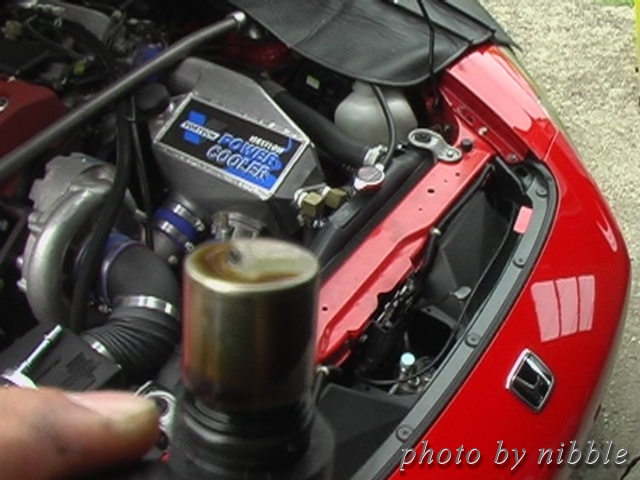
after everything was on, make sure not to leave any tool in engine compartment.... including rechet set on the crank.  I had this wierd noise, THARRRRRRRRRRRR, at over 1500 RPM
  good thing it was a premium tool. Hewww.
my impression on this work was very satisfactory. engine does idle and revs smoother. but for some others, it was critical. check this thread out. PICS it was a timebomb set to go off. this is another reason you should do this with expert.
cheers,
I had this wierd noise, THARRRRRRRRRRRR, at over 1500 RPM good thing it was a premium tool. Hewww.my impression on this work was very satisfactory. engine does idle and revs smoother. but for some others, it was critical. check this thread out. PICS it was a timebomb set to go off. this is another reason you should do this with expert.
cheers,


